
1.3 Volt Power Source
The described circuit serves as a versatile power source, specifically designed to replace 1.3V mercury cells or similar small batteries. It is particularly beneficial in applications where low voltage is required, such as powering digital thermometers or multi-adapter front panels in computer systems. The circuit harnesses power directly from a PC, utilizing its existing power supply outputs.
The power connectors are color-coded for ease of identification: the red and black wires deliver a 12V supply, while the black and yellow wires provide a 5V supply. This dual supply configuration allows the circuit to be adaptable to various devices that may require different operating voltages. However, caution is critical when working with these high current outputs, as the risk of short circuits is significant. To mitigate this risk, it is advisable to incorporate an inline fuse rated at 100mA, which will protect the circuit from potential damage due to overcurrent conditions.
The circuit derives the necessary 1.3V from a red LED. When the LED is forward-biased, it exhibits a typical voltage drop of approximately 1.9V across its anode and cathode. This voltage is higher than what is suitable for devices designed for mercury cell operation. To reduce the voltage to a more appropriate level, a 1N4148 signal diode is placed in series with the LED. The diode introduces a voltage drop of about 0.6V, effectively lowering the output voltage to approximately 1.3V, which is suitable for the intended applications.
This circuit design exemplifies an efficient method of utilizing readily available components to create a reliable power source for low-voltage devices, ensuring compatibility and functionality in modern electronic applications.This is a replacement power source for 1.3V mercury cells or other small batteries. It has many uses and I use this circuit in my computer to power a front panel multi adapter which has a digital thermometer. This circuit takes it power from a PC. The power connectors have colour coded wiring, red and black are a 12V supply, black and yellow are a 5V supply.
These are extremely high current so absolute care must be taken to avoid short circuits and an inline fuse of 100mA is recommended. The 1.3V is derived from a Red LED. When on and forward biased the LED`s voltage drop between anode and cathode is about 1.9V, this is too high for mercury cell powered equipment, but fed in series with a 1N4148 signal diode drops around 0.6V, the su 🔗 External reference
Related Circuits
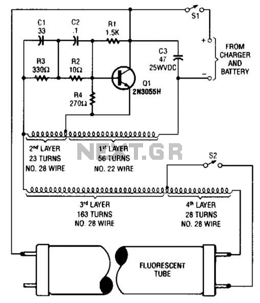
A 2N3055 oscillator (Q1) drives a homemade transformer, wound on a Vk ferrite rod. S2 is used as a filament switch and can be eliminated if desired. A 20-W fluorescent tube is recommended. The supply voltage is 12 V. The...
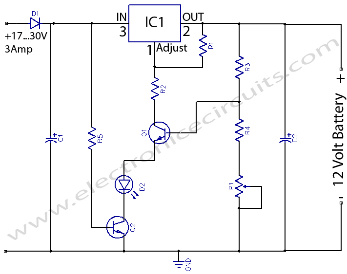
12 Volts Lead Acid Battery Charger Circuit. Apart from serving as a standard battery charger, this circuit is ideal for providing a constant charge to a 12-Volt lead-acid battery. This 12-Volt lead-acid battery charger circuit is designed to efficiently charge...

The title of this article raises the question of why the extensive selection of fully integrated voltage regulators should be supplemented with a version built using discrete components. Specifically, what advantages does this circuit provide that the well-known three-terminal...
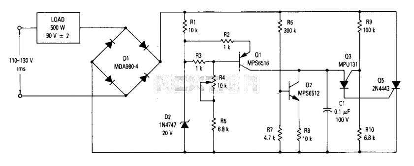
The circuit is an open-loop RMS voltage regulator designed to deliver 500 watts of power at 90 V RMS, maintaining good regulation within an input voltage range of 110-130 V RMS. When the input voltage is applied, capacitor C1...
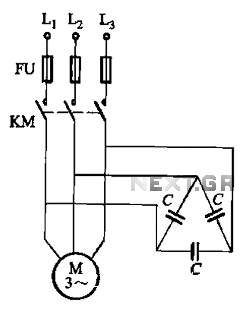
Asynchronous motor reactive power compensation involves directly connecting a capacitor to the stator windings of the asynchronous motor to enhance its power factor. This method is particularly effective for synchronous motors, as it reduces energy consumption related to reactive...
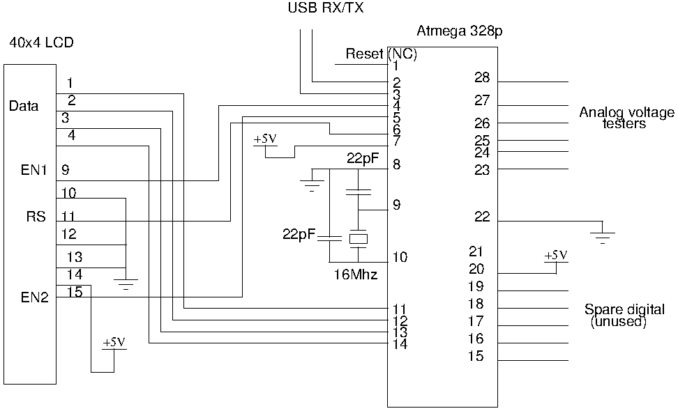
Drive a four-line LCD panel using an Arduino. The project initially aimed to control the LCD for displaying arbitrary information but evolved to include functionalities such as timekeeping, EEPROM read/write operations from the Atmel 328p, and voltage measurement. Multiple...
Warning: include(partials/cookie-banner.php): Failed to open stream: Permission denied in /var/www/html/nextgr/view-circuit.php on line 713
Warning: include(): Failed opening 'partials/cookie-banner.php' for inclusion (include_path='.:/usr/share/php') in /var/www/html/nextgr/view-circuit.php on line 713