
90Vrms voltage regulator
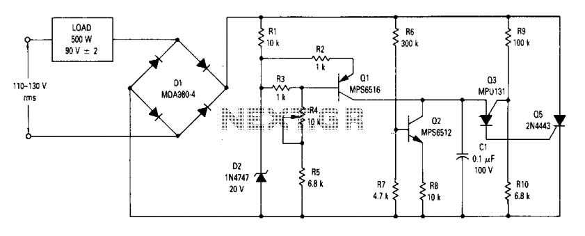
The open-loop RMS voltage regulator circuit operates by utilizing a combination of capacitors, resistors, and transistors to maintain a stable output voltage despite variations in input voltage. The primary components include capacitor C1, which plays a critical role in timing the activation of Q3, a key transistor that regulates the circuit's operation. The charging of C1 is influenced by the input voltage, and its charge level determines when Q3 will fire.
Resistor R10 is crucial for sensing the input voltage; as the input voltage increases, the voltage drop across R10 increases, which effectively raises the threshold for Q3's activation. This feedback mechanism ensures that the output voltage remains stable by adjusting the timing of Q3's firing in response to input voltage fluctuations.
Transistor Q5 serves as the main switch that controls the flow of current to the load. When Q3 is activated, it turns on Q5, allowing current to pass through and power the connected load. The circuit's design ensures that as the input voltage increases, the delay introduced by the increased firing point of Q3 compensates for the higher input, maintaining a consistent output voltage.
In scenarios where the input voltage decreases, the feedback loop operates in reverse. The voltage across R10 decreases, lowering the firing point of Q3, which allows for quicker activation of Q5, thus maintaining the output voltage within the desired range. This dynamic response to input voltage changes highlights the circuit's robustness and effectiveness in providing regulated power output.
Overall, this open-loop RMS voltage regulator circuit is an efficient solution for applications requiring stable voltage levels, particularly in environments where input voltage may vary significantly. The careful selection of components and their arrangement within the circuit contributes to its performance and reliability in delivering consistent power.The circuit is an open loop rms voltage regulator that will provide 500 watts of power at 90 V rms with good regulation for an input voltage range of 110-130 V rms. With the input voltage applied, capacitor Cl charges until the firing point of Q3 is reached causing it to fire.
This turns Q5 on which allows current to flow through the load. As the input voltage increases, the voltage across R10 increases which increases the firing point of Q3. This delays the firing of Q3 because Cl now has to charge to a higher voltage before the peak-point voltage is reached.
Thus the output voltage is held fairly constant by delaying the firing of Q5 as the input voltage increases. For a decrease in the input voltage, the reverse occurs. 🔗 External reference
Related Circuits
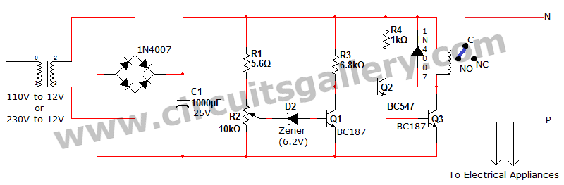
Voltage fluctuation is a significant concern in residential settings. For various reasons, the supply voltage may exceed 110V or 230V. This excessive voltage can potentially damage household electrical devices. An effective solution for electrical protection is the implementation of...
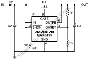
To protect downstream circuits from overvoltage conditions that occur during load-dump events or transients, the MAX6495, MAX6499, MAX6397, and MAX6398 can be utilized. The MAX6495, MAX6499, MAX6397, and MAX6398 are integrated circuits designed for overvoltage protection in various electronic applications....
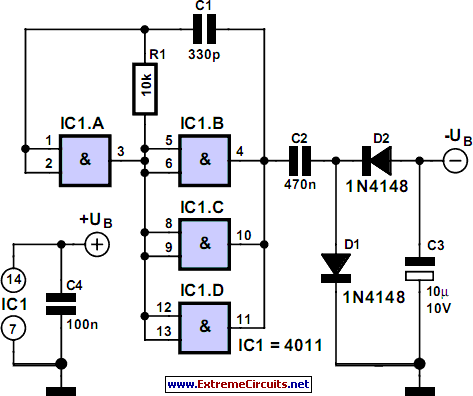
Some circuits require a negative supply voltage that only needs to deliver a small current. Providing a separate transformer winding for this purpose, potentially with a rectifier and filter capacitor, would be an extravagant solution. An alternative approach involves...
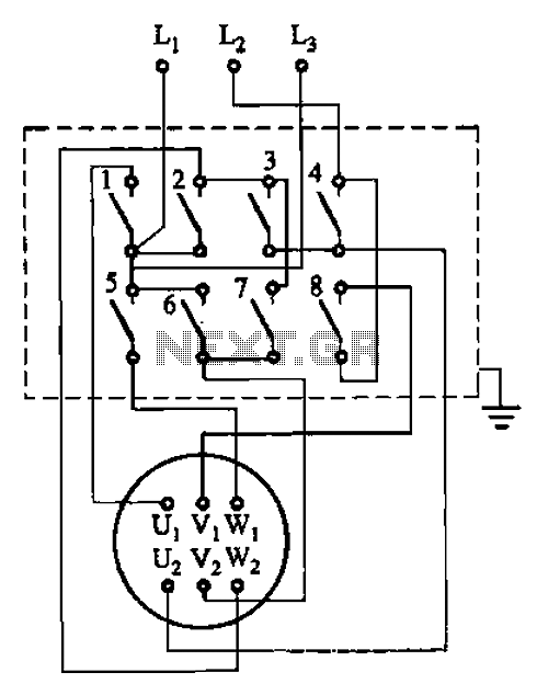
The circuit illustrated in Figure 3-36 includes the starter contact closure detailed in Table 3-1. In the figure, U1, V1, W1, and U2, V2, W2 represent the first three-phase stator windings of the motor terminals. The circuit depicted in Figure...
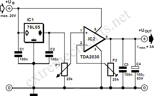
This adjustable voltage regulator is created by combining a standard 78L05 with an integrated audio amplifier of the type TDA2030, resulting in an adjustable voltage regulator. The circuit utilizes the 78L05 voltage regulator, which is a low dropout linear regulator...
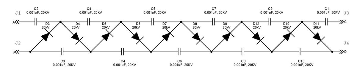
The Cockcroft-Walton multiplier employs a series of diodes and capacitors arranged in a cascade to generate a high-voltage DC potential from an AC input. This circuit topology utilizes diodes to charge capacitors in parallel and discharge them in series....