
1.3 Volt Power Source
The described circuit functions as a power supply replacement for 1.3V mercury cells, commonly utilized in various portable electronic devices. The design is particularly advantageous for applications requiring low voltage and compact power sources, such as digital thermometers and multi-adapter panels.
To construct this circuit, a step-down voltage regulator can be employed to convert a higher voltage input (e.g., from a standard 5V or 9V source) to the required 1.3V output. This allows for flexibility in power supply options while ensuring compatibility with devices that originally relied on mercury cells.
The circuit may include a capacitor at the output to stabilize the voltage and filter any noise, ensuring a clean power supply to sensitive components like digital thermometers. Additionally, a diode can be integrated to prevent reverse polarity, protecting the circuit from potential damage.
For implementation, the circuit should be designed with appropriate current ratings to match the power requirements of the connected devices. It is also advisable to consider thermal management, especially if the circuit is expected to operate continuously or under varying load conditions.
In summary, this power source circuit serves as a versatile and environmentally friendly alternative to traditional mercury cells, providing reliable and efficient operation for a range of electronic applications.This is a replacement power source for 1.3V mercury cells or other small batteries. It has many uses and I use this circuit in my computer to power a front panel multi adapter which has a digital thermometer. 🔗 External reference
Related Circuits
The schematic diagram originates from a 70W switching power supply utilizing the KA2S0880 IC. This power supply is designed for a 70W stereo amplifier and incorporates all necessary components for its primary operation. The KA2S0880 chip is known for...
The UCD90124/A is utilized to monitor multiple voltages, some of which exceed 2.5V. Scaling circuits are implemented to prevent exceeding the 2.5V maximum on the MON inputs. The inquiry pertains to whether raw voltage values or scaled values should...
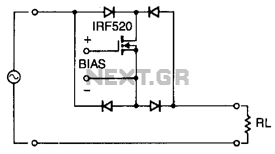
Utilizing four diodes in an array enables the use of a single MOSPOWER transistor for analog switching. The current flow is managed by maintaining the source-base connection of the MOSFET towards the load. It is essential to select diodes...
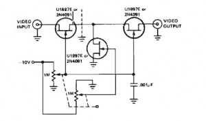
A variable gain amplifier controlled by voltage, functioning as a video amplifier. It utilizes three Field Effect Transistors (FETs) of type U1897E, which can be substituted with 2N4091. The described variable gain amplifier is designed to adjust its gain based...
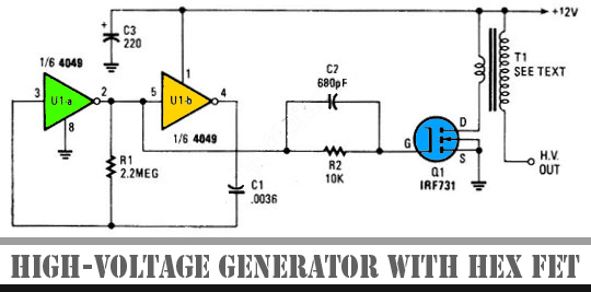
The schematic diagram below illustrates a high voltage generator circuit. This circuit employs a 4049 hex inverter configured as an oscillator, and it can utilize an ignition transformer from an automotive engine. A fly-back transformer may also be suitable....
This is a simple circuit of a Positive Voltage Doubler. This circuit utilizes the MAX1044/ICL7660. The Schottky diode was selected to reduce the voltage drop. The Positive Voltage Doubler circuit is designed to convert a lower input voltage into a...
Warning: include(partials/cookie-banner.php): Failed to open stream: Permission denied in /var/www/html/nextgr/view-circuit.php on line 713
Warning: include(): Failed opening 'partials/cookie-banner.php' for inclusion (include_path='.:/usr/share/php') in /var/www/html/nextgr/view-circuit.php on line 713