
70 W switching power supply

The schematic for the 70W switching power supply using the KA2S0880 IC illustrates a well-structured power conversion system suitable for audio amplification applications. The KA2S0880 integrates several essential components, including the power switch, control circuitry, and feedback mechanisms, which contribute to its efficient operation. The input section receives power from a 9V battery, which is then processed by the switching regulator to yield a stable 5V output.
The switching regulator operates by rapidly turning the transistor Q1 on and off, allowing for efficient energy transfer and minimizing heat generation. The increased collector voltage during the 'on' state facilitates current delivery to the load. The design is optimized for an efficiency of 80%, which is indicative of a well-engineered circuit that balances performance and thermal management.
In addition to the 5V output, the circuit also features a 12V/2A switching power supply. This component is crucial for applications requiring higher voltage and current levels. The output stage of this power supply is designed to maintain a stable 12V output while delivering up to 2A of current, making it suitable for driving various electronic loads.
The necessity for a bipolar supply of -60V is addressed through the implementation of a flyback converter topology, controlled by the UC3842 PWM controller. This configuration allows for voltage scaling and flexibility in output parameters, making it adaptable for various applications, including powering notebook computers at 20V.
Overall, the schematic diagram represents a robust and efficient power supply solution, with the KA2S0880 and UC3842 providing a foundation for reliable performance in audio amplification and other electronic systems.The schematic diagram come from circuit: 70 W Switching Power supply with KA2S0880 IC power supply. Go to that page to read the explanation about above power supply related circuit diagram. The schematic shows the power supply capacity of 70W stereo amplifier Power converter is built on a chip KA2S0880, which includes all the necessary components to build the primary of the power supply. This chip is very stable in operation. This simple switching regulator circuit have 5 V output, the input provide by a 9 V battery. It having 80% efficiency and 50mA output capability. How simple switching Regulator works: While Q1 is actually on, its collector voltage increases, delivering current. The circuit 12 volt / 2 A switching power supply in the above scheme is not too complicated. At the output of this block provides a stable 12 V and maximum current 2A. Power supply units are quite compact and. The main part of any amplifier is the power supply. It is clear that to obtain a high output 12-volt battery is not enough. Therefore, we must first create a voltage converter, which enables a bipolar supply -60V with a. The scheme is a classical flyback power supply for PWM UC3842. Since the scheme`s base power supply output parameters can be easily converted to the necessary. As an example, for the consideration of selected Power supply for Notebook Power 20V. We aim to transmit more information by carrying articles. Please send us an E-mail to wanghuali@hqew. net within 15 days if we are involved in the problems of article content, copyright or other problems.
We will delete it soon. 🔗 External reference
Related Circuits
This circuit utilizes a 74HC14 hex Schmitt trigger inverter as a square wave oscillator to drive a small signal transistor configured in a class C amplifier setup. The frequency of the oscillator can be either fixed using a crystal...
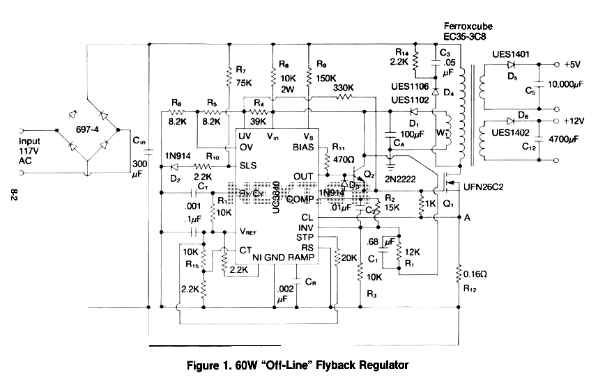
This paper gives a practical example of the design of an off-line switching power supply. Factors governing the choice of a discontinuous flyback topology are discussed. The design uses a pulsed-width modulation (PWM) control scheme implemented with a Unitrode...
This project began with the exploration of arc starters that could be built at minimal cost using materials typically found in a tinker's workshop. Although it has been an enjoyable endeavor, the extensive collection of items in the basement...
An increasing number of appliances draw a very small current from the power supply. If designing a mains-powered device, one can generally choose between a linear and a switch-mode power supply. However, when the appliance's total power consumption is...
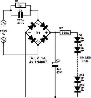
An array of white LEDs can serve as a compact lamp for living spaces. These LED lamps are commercially available and resemble standard halogen lamps, fitting into typical 230-V light fixtures. Upon inspection, it is evident that a capacitor...
The 7915 (at least the "made in Morocco" I used) needs a small load (some mA) to work correctly. If you get funny voltages (-18.4V or so), put a resistor from the 7915 output to ground (2k2 works good)....