
Over Voltage Protection
The described circuit employs a thyristor-based crowbar protection mechanism to safeguard sensitive electronic components from transient voltage spikes. The primary function of this circuit is to provide rapid response to over-voltage conditions, which can occur due to various factors such as inductive load switching, lightning strikes, or other electrical disturbances.
In the circuit, a Zener diode is utilized to establish a predetermined voltage threshold. When the power supply voltage exceeds this threshold, the Zener diode conducts, causing a voltage rise across a connected 4.7k ohm resistor. This voltage increase triggers the thyristor, which is designed to activate within microseconds, effectively creating a low-resistance path to ground. This rapid action results in the power supply rails being short-circuited, thereby diverting excess voltage away from sensitive components.
The duration of the short circuit is critically limited to a few milliseconds, allowing for the immediate reduction of voltage before the primary fuse in the circuit blows. This delay is crucial as it mitigates the risk of damage to components that may not withstand high transient voltages. The fuse serves as a secondary line of defense, ensuring that the circuit is ultimately protected from sustained overcurrent conditions that could arise if the thyristor remains conductive for an extended period.
Simulation tools, such as TINA, can be used to analyze the circuit's performance under transient conditions, providing visual representations of voltage and current waveforms. This simulation can help in understanding the effectiveness of the crowbar circuit in real-world scenarios, illustrating the rapid response time and the effectiveness of the protective measures implemented in the design. Overall, this circuit is an essential component in applications where transient voltage spikes pose a significant risk to electronic devices.Safety devices like fuses provide protection against excess current, but do nothing for transients and short duration spikes of high voltahe on the power supply lines.This circuit uses the "crowbar" method and provides fast protection against transient voltage spikes, transients that could cause damage to sensitive components. The thyristor will trigger in a few microseconds. This is over 1000 times faster than an ordinary quick blow fuse. If the output voltage exceeds the limit set by the zener, then it will conduct. The voltage across the 4.7k resistor will rise, the thyristor switches on and the power rails are short circuited.
The duration of the short circuit will be only a few milliseconds before the fuse blows. In these few milliseconds the voltage will be greatly reduced. Below is a simulated transient plot, using the TINA program. In the circuit above, and the graph the tr 🔗 External reference
Related Circuits
Over-Temperature Alarm Circuit Uses Common, Inexpensive Components | Negative-temperature-coefficient (NTC) thermistor, ICs. The Over-Temperature Alarm Circuit is designed to detect excessive temperatures and provide an alert using readily available and cost-effective components. The core sensing element of this circuit is...

This motor overload circuit allows for short-term overdriving of a system, which is dependent on heat buildup. An overload detection circuit safeguards the motor against currents exceeding the rated current for specific exposure durations. The permissible exposure times are...

The circuit illustrated in Figure 3-47 involves a three-phase AC motor that is initially connected through a step-down autotransformer. To initiate operation, the power switch is closed, and the operating handle is pushed to the start position. Once the...

This circuit indicates which of three voltages in the range from approximately -4V to +4V at points A, B, and C is the highest by illuminating one of three indicators. The circuit is designed to compare three input voltages, labeled...
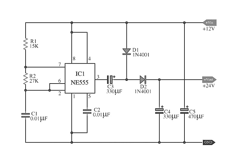
The capacitors C5 work in conjunction with IC1, while the resistors R1 and R2, along with capacitors C1, form an astable multivibrator square wave generator. This generator outputs a frequency of approximately 2 kHz from pin 3 of IC1....

The circuit is designed for high precision operation over an extended temperature range, provided that V+ remains relatively constant, as the current IZ is dependent on V+. Resistors R1, R2, R3, and R4 are selected to ensure the appropriate...