
1.8MHz AM transmitter and receiver

The Chatterbox transmitter and receiver system is designed to provide effective communication for local amateur radio operations. The modular approach allows for flexibility in integration with existing equipment, making it suitable for various configurations. The use of the TDA1072A chip ensures cost-effectiveness while maintaining adequate performance for the intended application. Careful attention to the construction of filters and tuning components is essential for optimal signal quality. The incorporation of additional features from the TDA1072A chip can enhance functionality and provide users with more control over their reception capabilities. Overall, this design serves as a practical solution for amateur radio enthusiasts seeking to establish reliable communication within their local networks.Before starting on the receiver side of the` Chatterbox`, we ought to take a final look at the transmitter itself. The Chatterbox transmitter is built separately, because many constructors will want to use it in conjunction with an existing receiver on 1.
8MHz. It`s been assumed that an existing antenna tuner and low-pass filter unit will be used w ith the transmitter. However, if you intend to use the complete transmitter and receiver combination as a `stand alone` unit, it will be necessary to use a suitable low-pass filter to reduce potential harmonics. A filter of this sort can be built into the transmitter, or it can be an outboard type used in conjunction with a small antenna tuner.
What the individual constructor does of course, will depend on the size of casing and whether or not the project is built as separates or as one small unit. With the change-over switching described in the previous article, the transmitter can be used with any 1.
8MHz receiver. If you don`t have a suitable set, you can add a simple single board receiver of the sort described here. However, bear in mind that the receiver is not a DX model and it`s designed for using the Chatterbox combination in local a.
m. nets. The receiver section is based on the TDA1072A a. m. receiver i. e. This is an inexpensive chip which performs all the functions of an a. m. receiver between the antenna and the audio stages. The TDA1072A`s sensitivity and signal handling capabilities are such that it`s suitable for this application. The i. e. also supports several features not used in this design. Some of the features are made available on the p. c. b. , should you wish to incorporate them in the receiver. For example, the chip provides an S-meter output, a muting facility and a buffered oscillator output for driving a frequency counter.
The circuit is shown in Fig. 2. 1, and it closely follows the manufacturer`s specification sheet. The incoming signal is filtered with a high-passfilter, L6 (wound on a toroid) and associated capacitors, and a two stage band-pass filter, comprising of T2 and T3. The high-pass filter was included because the receiver operates close to the medium wave broadcasting band.
Winding the toroid for L6 is a simple job and it only requires a little concentration for a neat job. All you need to do is wind 24 turns of 0. 4 or 0. 5mm enamelled copper wire on a T37-2 core. I have a local commercial broadcasting station at the top end of the medium waveband that can light bulbs in my location in Rochdale!
The high-pass filter was included to kill the pop music breakthrough. The band-pass filter has manual tuning provided by a polyvaricon capacitor, C36, to peak the wanted band signals and reduce the out-of-band signals. The band is tuned using a variable capacitor, C39, in conjunction with T4. Although the TDA 1072A was designed for varicap tuning, this arrangement allows for very stable tuning over the band.
The variable capacitor, C39, is a standard value, 75pF, (a 100pF may be used as an alternative) which more than covers the whole band. This tuning capacitor is mounted directly on the printed circuit board. The ground connection on C39, is made through the mounting nut to the p. c. b. To avoid any problems with poor connections, I also added a wire between the tag to the moving vanes and the ground plane on the top of the printed circuit board.
The i. f. at455kHz, is filtered by using a CFW455HT ceramic filter and an i. f. transformer, T5, placed between the mixer output, pin 1, and the i. f. amplifier, pins 3 and 4. It`s possible to inject a b. f. o. signal at pin 4, to make the receiver available for c. w. and s. s. b. reception. Several radio amateurs have used this i. e. to make a c. w. and s. s. b. receiver. I tried injecting a 455kHz signal at pin 4, but found that it triggered the internal a. g. c. This reduced the overall gain of the receiver, to what I considered to be an un 🔗 External reference
Related Circuits
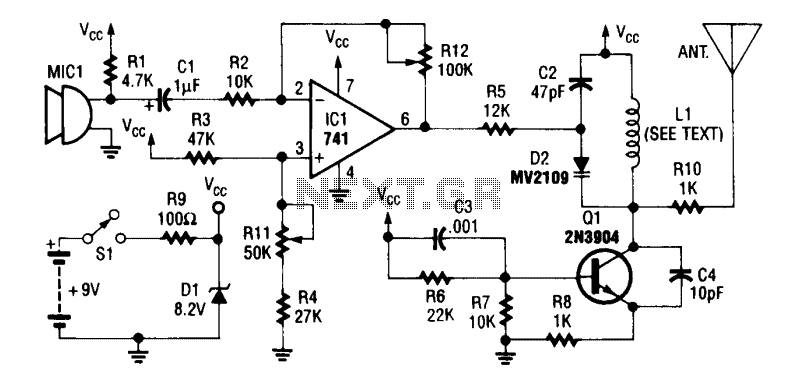
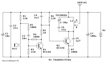
An operational amplifier integrated circuit (741) amplifies the audio signal from microphone MIC1, with resistor R12 adjusting its gain. The amplified audio is directed to the oscillator circuit, which includes transistor Q1 and associated components. D2 is a varactor...
The OPT301 is housed in a TO-99 8-lead package, offering good sensitivity with a bandwidth limited to 4 kHz. Its peak response is in the infrared region at 750 nm, while sensitivity in the visible red spectrum at 670...
The TDA7000 is a well-known FM radio receiver integrated circuit (IC), also referred to as a one-chip FM radio receiver. It operates within the VHF FM band, covering frequencies from 70 to 120 MHz. Introduced in the 1980s, the...
A 40kHz ultrasonic transmitter circuit consists of three oscillators (F1, F2, and F3), with F3 generating a 40kHz square wave output. The frequency is primarily determined by components C1, R1, and an adjustable resistor (RP). The excitation output from...
This is a simple and low-cost FM transmitter circuit. The frequency range of this FM transmitter is approximately 89 MHz to 109 MHz, with an output power of about 9 mW at 9 V. The circuit includes the following...
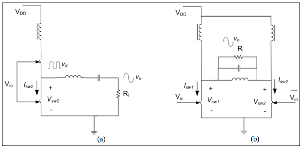
The measured output power and efficiency of a 6 dBm 130nm CMOS class-D inverter chain was analyzed, utilizing gate bias variation to generate a pulse width modulated inverter output voltage (Cijvat et al., 2008). Efficiency versus output power was...