
1 Cell battery LED flasher circuits
The LED flasher circuits described operate efficiently on a single 1.5-volt battery, demonstrating various configurations to achieve different flashing rates and brightness levels. The circuit utilizing the LM3909 IC is particularly noteworthy for its simplicity, requiring only a timing capacitor and an LED, which makes it ideal for basic applications.
The circuit designed by Andre De-Guerin employs a 100uF capacitor to effectively double the voltage supplied to the LED, achieving 3 volts for operation. This is accomplished using two sections of a 74HC04 hex inverter configured as a square wave oscillator, which generates the necessary frequency for the LED flashing. The third section of the inverter acts as a buffer, charging the capacitor through a 470-ohm resistor when the output is high (+1.5 volts). Upon switching to ground (0 volts), the charged capacitor discharges through the LED and the battery, providing sufficient voltage to illuminate the LED.
The typical forward current for the LED in this configuration is around 3 mA, necessitating the use of a high-brightness LED to ensure adequate visibility. The design can be modified by incorporating additional transistors in the other two circuits, which enhance the discharge rate of the capacitor, thereby increasing the current to approximately 40 mA at peak. This is particularly useful for applications requiring higher brightness or longer flash durations.
For extended flash durations, the use of a larger capacitor, such as a 1000uF, in conjunction with a 33-ohm resistor, can lengthen the flash duration to approximately 50 milliseconds. Additionally, in the discrete 3 transistor circuit configuration, it is recommended to add a resistor of about 5K in series with a 1uF capacitor to effectively widen the pulse width, thus allowing for greater versatility in the flashing characteristics of the LED.
Overall, these circuits exemplify a range of techniques for LED flashing applications, showcasing the effective use of voltage doubling, oscillation, and timing components to achieve desired operational characteristics.The LED flasher circuits below operate on a single 1.5 volt battery. The circuit on the upper right uses the popular LM3909 LED flasher IC and requires only a timing capacitor and LED. The top left circuit, designed by Andre De-Guerin illustrates using a 100uF capacitor to double the battery voltage to obtain 3 volts for the LED.
Two sections of a 74HC04 hex inverter are used as a squarewave oscillator that establishes the flash rate while a third section is used as a buffer that charges the capacitor in series with a 470 ohm resistor while the buffer output is at +1.5 volts. When the buffer output switches to ground (zero volts) the charged capacitor is placed in series with the LED and the battery which supplies enough voltage to illuminate the LED.
The LED current is approximately 3 mA, so a high brightness LED is recommended. In the other two circuits, the same voltage doubling principle is used with the addition of a transistor to allow the capacitor to discharge faster and supply a greater current (about 40 mA peak). A larger capacitor (1000uF) in series with a 33 ohm resistor would increase the flash duration to about 50mS.
The discrete 3 transistor circuit at the lower right would need a resistor (about 5K) in series with the 1uF capacitor to widen the pulse width. 🔗 External reference
Related Circuits

This page outlines the hardware and software design of a printer power switch that is controlled via USB from a Linksys NSLU2, also referred to as Slug. Although primarily designed for printer control, the unit can manage any device...

A high-quality preamplifier with tone controls consisting of three circuits. The NE5532 is chosen as the main integrated circuit due to its ultra-low noise properties, making it a popular choice in fine audio applications. Although these circuits are older...

A system has been developed that employs eight air-clamping cylinders (McMaster-Carr 62185K64) to apply pressure on a glass piece, sealing it to a sidewall. However, the glass has cracked multiple times, prompting the need for a cost-effective method to...
This is a simple yet effective darkness activator. It uses a light-dependent resistor (LDR) to detect light, and when no light is present, it activates an alarm from an 8-ohm speaker. The circuit can be easily modified to function...
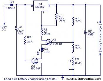
The circuit is designed as a constant voltage source with a negative temperature coefficient. The transistor Q1 (BD 140) serves as the temperature sensor, while transistor Q2 prevents battery discharge through resistor R1 when mains power is unavailable. The...
The following circuit illustrates a Dancing LEDs electronic circuit diagram. This circuit is based on the LM358 integrated circuit. Features: IC1A amplifies the signal. The Dancing LEDs circuit utilizes the LM358 operational amplifier to create a visually appealing light display....