
1 hour timer circuit with 4011 and 4020 ICs
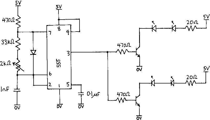
The schematic for this circuit consists of two primary sections: the astable multivibrator and the 14-stage ripple counter. The astable multivibrator formed by gates U1 and U2 operates based on the resistor-capacitor (RC) time constant, which determines how quickly the output toggles between high and low states. The timing components are critical; the resistor R1, which includes a variable preset resistor, allows for fine adjustments to the timing period, while C1's value influences the frequency of oscillation.
The output from the astable multivibrator feeds into the clock input of the 4020 binary counter (U3), which counts the incoming pulses and divides them down. The Q13 output pin of the counter acts as a signal that indicates when the counter has received 2048 pulses, activating the sounder connected to it.
Gate U4 modulates the sounder by controlling its on/off state in synchronization with the oscillator's output, thus producing a sound pattern that corresponds to the timing interval set by the astable multivibrator. This modulation can be adjusted by varying the input to U4.
The circuit's design allows for versatile applications, including timing mechanisms for parking meters or other timing-related functions, with the ability to customize timing intervals through the selection of resistors and capacitors. The use of CMOS technology ensures low power consumption, making this circuit suitable for battery-operated devices.
For simulation purposes, LT Spice provides an effective platform to visualize the circuit behavior, allowing for adjustments and optimizations before physical implementation. The graphical output from the simulation can guide further refinements to the timing and modulation characteristics of the circuit, ensuring reliable operation in practical applications.This circuit uses just two CMOS IC`s, a 4011 quad 2 input NAND gate, and a 4020 14-stage ripple binary counter. At switch on R2 and C2 provide a brief reset pulse, which will ensure the output pin Q1 of the 4020 is high.
Gates U1 and U2 form a simple astable R1 and C1 determining the timing period. The tolerances of capacitors vary widely, so for more control, you may use a 470n capacitor for C1 and use a fixed 3. 3M resistor in series with a 250k preset for R1. A timing period of just less than 1. 76seconds is required. The output of the oscillator at U2 drives the input of the 14-stage ripple counter, U3. The outputs divide sequentially by two and the output signal is taken from Q13, requiring 2048 input pulses before the signal becomes high. When the output Q13 goes high, the output sounder will become active. Gate U4 of the 4011 is used to "modulate" the output sounder. As U4 is also connected to the output of U2, the output sounder will turn on and off at the same rate as the oscillator.
Suitable output sounders can be found at Maplin Electronics part code KU56L or CR34M. These are self contained DC piezo buzzers, requiring 10mA at 12V DC but work with supply voltages from 3 to 15 Volts DC. A downloadable simulation version is available here. This has been tested with LT Spice version IV. From version 4. 05 onwards, transient simulation can take a long time. To speed up simulation, I have set initial conditions on the circuit node connected to gate U1 to zero.
This speeds up simulation time to a matter of seconds. LT Spice is a freely available schematic capture and spice simulator program made by Linear Technology. The link to their software page is here. There is also an active yahoo group available for LT Spice which you can find here. The graph below is from the simulation version of this circuit. In the simulated version I have tapped the output of the CMOS4020 at Q5, therefore only 8 input pulses from the oscillator (shown in green trace) are required before theQ5 output switches to high (shown as blue trace).
The top waveform in red, is the output across the output sounder. As can be seen, this output is switched on and off as long as the output pin, Q5 is active. To simulate the sounder, I have used a fixed resistor. Here comes the maths. One hour or 3600 seconds divided by 2048 pulses (Q13) requires a timed period of 1. 7578 seconds. The timing for a CMOS oscillator, varies with supply voltage, but is approximately 1. 1 RC. To achieve the timed period, C1 is 0. 47u and R1 is made from a fixed 3. 3M resistor in series with a 250k preset. To adjust this value, connect a low current LED and fixed 2. 2k resistor to the output of IC2. The LED should illuminate on each pulse. Adjust the 250k preset until the LED flashes about 34 times per minute (60/34 = 1. 76s). If you would like to use this a parking meter timer, then set the unit to trigger before the hour is up or start the timer before you feed the meter to allow extra time. 🔗 External reference
Related Circuits
Picture a morning where you are anxiously waiting for the bus to work, only to realize that you cannot find your keys. If this scenario occurs often, this circuit is designed for you. A simple press of a button...
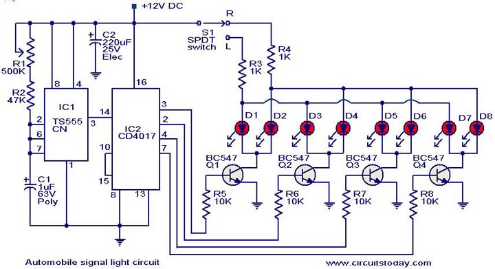
This is a simple circuit that can be used as a sequential signal light in automobiles. The circuit is based on two integrated circuits (ICs): a TS 555 CN CMOS timer IC and a CD4017 decade counter IC. The...
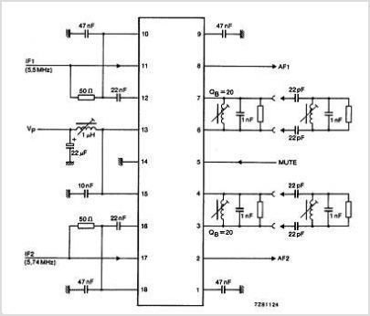
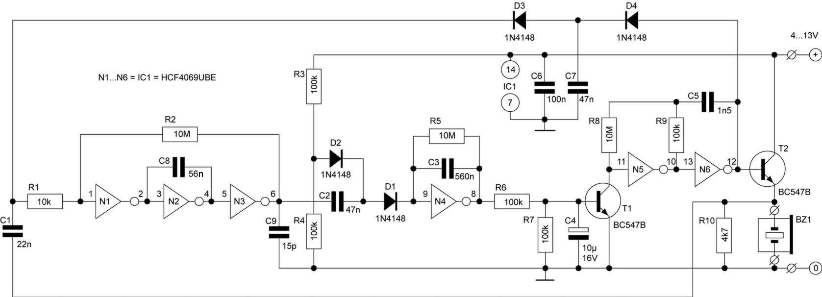
The TDA3567 is a monolithic integrated decoder designed for the NTSC color television standards. It incorporates all the necessary functions for the demodulation of NTSC signals. Additionally, it features a luminance amplifier and an RGB matrix amplifier. These amplifiers...
The T-40-16 and 555 ultrasonic transmitter circuit configuration consists of an ultrasonic transmitter T-40-16 and a 555 timer circuit. By adjusting the potentiometer RP, the oscillation frequency of the circuit can be changed. The output pulse frequency from the...

This is a simple circuit design for a two-station intercom system utilizing common 8-ohm mini speakers. The press-to-talk switches should feature a spring-return mechanism to ensure that the intercom cannot be left in the ON position. The circuit requires...
The infrared receiver requires the infrared light to be modulated at 38 kHz, which corresponds to a period of 26 µs. The specifications for the receiver suggested using a 50% duty cycle; however, this configuration did not perform as...
Warning: include(partials/cookie-banner.php): Failed to open stream: Permission denied in /var/www/html/nextgr/view-circuit.php on line 713
Warning: include(): Failed opening 'partials/cookie-banner.php' for inclusion (include_path='.:/usr/share/php') in /var/www/html/nextgr/view-circuit.php on line 713