
autonomous mobile robot capable of avoiding obstacles circuit
The infrared receiver is a critical component in robotic applications, particularly in obstacle detection and navigation systems. The modulation of infrared light at 38 kHz ensures optimal performance of the receiver, as it is tuned to respond to this frequency while remaining sensitive to a broader range. The choice of a 5% duty cycle over the initially suggested 50% enhances the reliability of signal detection, reducing the likelihood of false positives when interpreting sensor data.
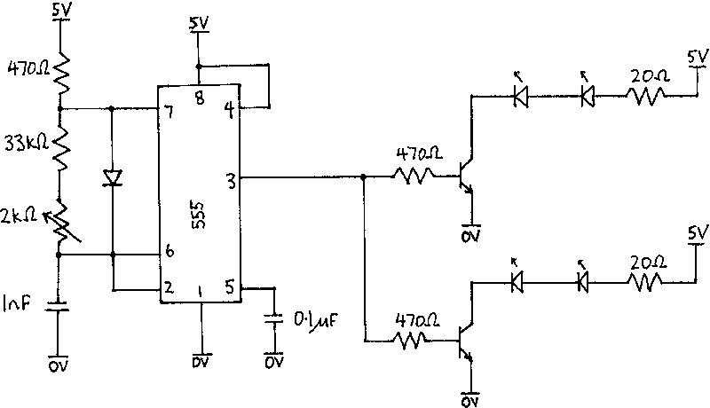
The use of four 6mm infrared LEDs strategically positioned across the front of the robot maximizes the sensor's effective field of view, ensuring comprehensive coverage for obstacle detection. The 555 timer serves as an efficient means of generating the required modulation frequency, with the trimpot allowing for precise tuning to match the receiver's specifications. This level of control is essential for ensuring that the signal remains within the acceptable frequency range, thereby minimizing interference from extraneous light sources.
The integration of the ATMEL 89C2051 microcontroller facilitates advanced control logic, enabling adaptive responses based on sensor inputs. The design allows for reprogramming, which is advantageous for iterative development and testing. The connection of the microcontroller to the L293E motor driver circuit provides a robust mechanism for controlling motor functions, allowing for directional changes based on obstacle detection.
The implementation of a basic filtering strategy to mitigate signal flickering demonstrates a practical approach to improving sensor reliability. By requiring a sustained high signal before registering an obstacle, the system reduces the impact of transient noise, resulting in smoother navigation and enhanced operational efficiency. The division of the project into distinct subsystems—sensor, motor driving, and logic—ensures a modular design, facilitating troubleshooting and future enhancements. Overall, this project exemplifies the integration of various electronic components to achieve a cohesive and functional robotic system.The infra-red receiver requires the infra-red light to be modulated at 38 kHz, this is quivalent to a period of 26 µs. The specifications on the receiver suggested using a 50% duty cycle. We found however that this did not work the way we intended. To overcome this we reduced the duty cycle to 5%. The infra-red sources used were 6mm infra-red (88 0 nm) LEDs. Using a bank of four of these LED`s across the front of the robot gave an even coverage in the sensor ’s field of view. To modulate the light we drove the infra red LEDs using a 555 timer chip. This timer was tuned using a trimpot to give exactly 38 kHz, which is the receiver ’s centre frequency, however the receiver is susceptible to frequencies between 25 khz and 60 kHz.
The output pin of this timer chip drove the two infra-red LEDs. An ATMEL 89C2051 micro controller was used to control the operation of the dieBot. The benefit of using a micro controller is that the function of the robot can be reprogrammed. This allows for easy design, redevelopment and dubugging. The two inputs to the micro were the outputs from the left and right infra red sensors. There were four outputs from the micro that were connected the motor driving circuit (L293E). The logic of the controller was simple, if the robot sensed a object on the left it would turn right and visa versa. We found difficulties that the robot was very apprehensive when it approached an obstacle. It was found that the ouput signal from the infra red receivers was a digital signal and flickered greatly before changing state.
Some form of filtering had to be performed on the input signal. A crude form of filterering was achieved by waiting for the transmitter to detect high for a period of 0. 1 seconds before actually sensing an object. This method of filtering was successful and the operation of the robot performed a lot smoother. The design of DieBot was split into three main aspects the sensor system, motor driving system and the logic system.
The project has given all the team members an understanding in the following areas: 🔗 External reference
Related Circuits
The problem with class-B amplifier design is that we start with an output stage in two halves, each with a non-linear response, which we then add together to try to give a linear response, i.e. so that a graph...
This voltage-to-frequency converter circuit features a voltage-controlled oscillator with a deviation of 0.5%. The integrated circuit IC1 functions as a multivibrator, generating rectangular impulses of equal width. The output frequency is adjustable via the U1 voltage. The D3 diode...

This circuit describes the sensing of air flow using the PIC16C781 microcontroller. It utilizes Programmable Switch Mode Controllers (PSMC) that combine an Integrated Operational Amplifier, a Digital-to-Analog Converter (DAC), and a gated timer to create a thermally operated air...
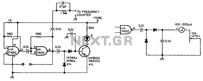
This circuit checks a crystal for activity. Two sections of a 7400 IC act as an oscillator, and its output is rectified to drive an NPN transistor that switches an LED. In an alternative configuration, a meter replaces the...
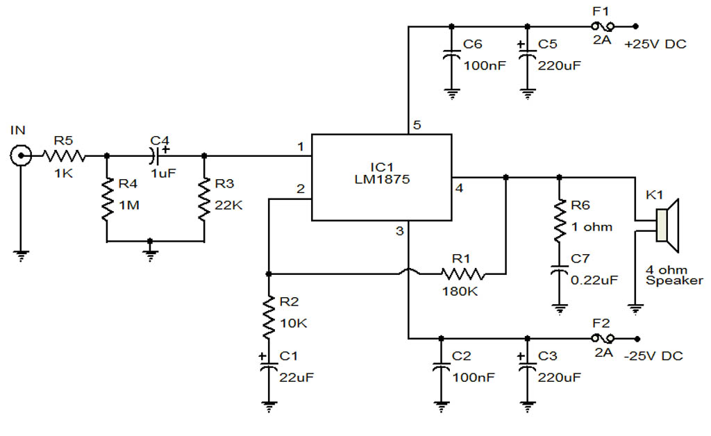
The circuit illustrates a 20-Watt audio amplifier diagram based on the LM1875 integrated circuit (IC). It is designed for use in automotive applications and provides an output power of 20 Watts. The 20-Watt audio amplifier circuit utilizing the LM1875 IC...
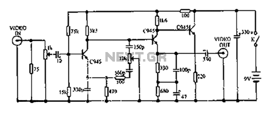
This circuit compensates for additional defects in image quality associated with LP (long play) recorders. The frequency components of the television signal reflect the details displayed on the screen. Enhancing the high-frequency components increases the edge sharpness of the...