
Ultrasonic remote control switch lighting circuit
The T-40-16 and 555 ultrasonic transmitter circuit is designed to operate efficiently in applications requiring remote control through ultrasonic signals. The T-40-16 ultrasonic transmitter is responsible for generating sound waves at a frequency of 40 kHz, which is above the range of human hearing, ensuring minimal interference from environmental noise. The 555 timer is configured in astable mode, allowing it to produce a continuous square wave output. The frequency of oscillation can be fine-tuned using the potentiometer RP, enabling flexibility in the operational range of the transmitter.
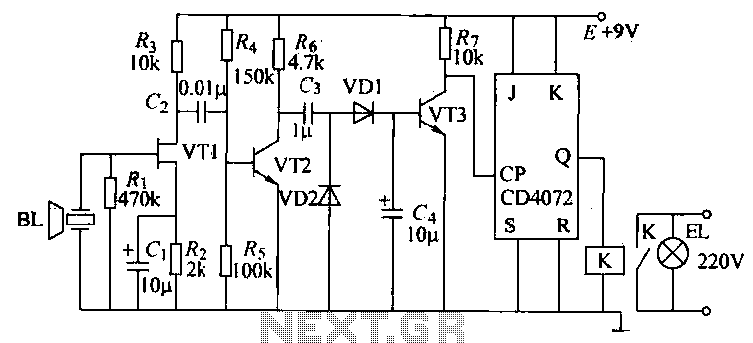
The receiver circuit, designated as R-40-16, is essential for detecting the ultrasonic signals emitted by the transmitter. It employs a multi-stage amplifier configuration to amplify the weak signals captured by the ultrasonic sensor. This amplification is crucial for ensuring that the signals are strong enough to trigger subsequent processing stages. The output of the amplifier is then shaped into a square wave, which is fed into a bistable multivibrator circuit formed by transistors VT5 and VT6. This circuit operates as a flip-flop, maintaining a stable output state until triggered by an incoming pulse.
When the ultrasonic signal is detected, the bistable circuit toggles its state, which in turn activates the relay (K). The relay is used to control various electrical loads, allowing for practical applications such as switching on or off devices remotely. The overall design of the circuit ensures reliable operation over a distance greater than 8 meters, making it suitable for various remote control applications. The use of a 9V power supply and a current draw of 40-45 mA indicates that the circuit is energy efficient, suitable for battery-operated devices or other low-power applications.T-40-16 and 555 ultrasonic transmitter circuit configuration as shown in a, the circuit consists of an ultrasonic transmitter T-40-16 and 555 circuit, adjust the potentiometer RP can change the oscillation circuit frequency. 3 feet from the oscillating pulse output 555 of 40kHz drive T-40-16 work, so that emit ultrasonic signals of 40kHz. Circuit operating voltage of 9V, operating current of 40 --45mA. Control distance is more than 8m. (2) R-40-16 Ultrasound crossing the receiving circuit shown in Figure 18-32b, the VT1-VT7 circuit and other components.
Since receiving the signal emitted by the transmitter is very weak, the circuit uses multi-stage amplifier, the output pulse signal crossing the square, to Zhu ~ VT5:. VT6 and related components, electrical bistable Lu Zealand to working condition i transistor VT4 conduction on each once (launchers once), the trigger signal by G, C bistable circuit to feed a trigger pulse.
VT5: '' VT6 reversed again. When VT6 when turned on from off, VT5, VT7 closing, relay K release and maintain. When the next pulse to the arrival time -VT6 conduction is turned off. VT7 conduction, the relay pull-K, control the work load. This circuit can be used for remote control of various electrical switches control.
Related Circuits
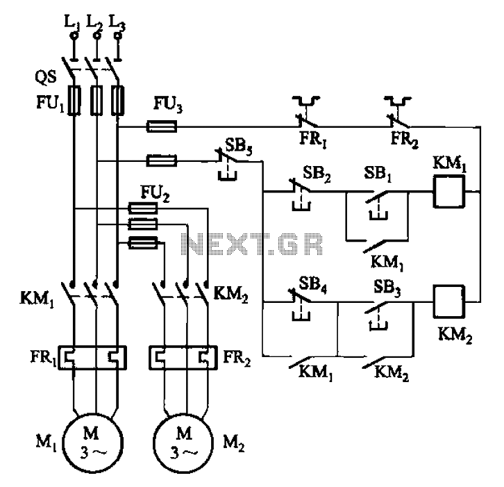
The circuit depicted in Figure 3-84 allows two electric motors to be started independently. The motors can only be activated after pressing the main stop button (SBz) to release contact KMi. Following this, the auxiliary stop button (SB4) can...
This circuit when used with a 555 timer will cause light emitting diodes to turn on and off more slowly. This will make the LEDs appear similar to incandescent lamps. The described circuit utilizes a 555 timer IC configured in...
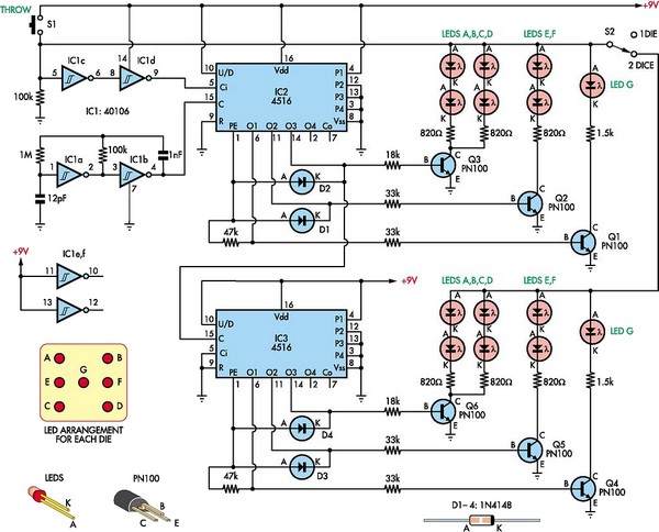
This circuit utilizes two 4516 integrated circuits (ICs) to simulate a game involving two dice. A switch is included to select whether one or two dice will be activated with each press. A 9-volt battery is sufficient for power...
This device is a long-standing controller for various home appliances, including night lights and air conditioners. It is a Miniature Real-time Controller that utilizes three primary components: an 89C2051 microcontroller, a DS275 or MAX232 level shifter, and a 74LS07...

A DC booster circuit is illustrated in the figure, which represents a step-up transformer circuit diagram. The step-up transformer (T) can be utilized to power small transistor radios. The winding ratio can be adjusted to achieve the desired output...
This infrared light valve has more parts, so it works better and more reliable for alarms. The circuit responds less ambient light. The light valve consists of a transmitter and a receiver. The transmitter consists of a NE 555...