
Automobile turn signal circuit
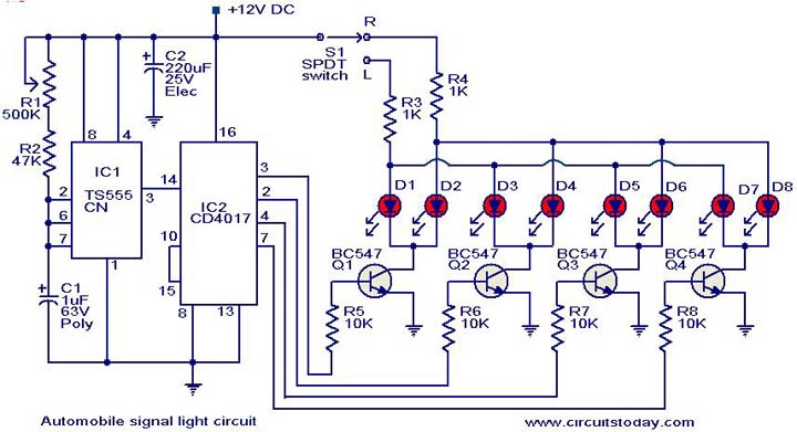
The described circuit utilizes the TS 555 timer IC configured in astable mode to generate a continuous pulse signal, which serves as the clock input for the CD4017 decade counter IC. The CD4017 features ten output pins, but in this application, only four outputs (pins 3, 2, 4, and 7) are utilized for sequentially illuminating the LEDs. The frequency of the output pulse from the TS 555 determines the speed of the LED sequencing, allowing for customization based on user preference or specific application requirements.
Transistors Q1 to Q4 act as switches to control the current flowing through each LED. When a particular output pin from the CD4017 goes high, the corresponding transistor is activated, allowing current to flow through its associated LED, thus illuminating it. The arrangement of the LEDs should follow the vehicle's left and right turn signal configuration, ensuring that the correct side lights up in response to the turn signal activation.
The switch S1 is incorporated to facilitate the selection of the turn signal direction. When the switch is toggled, it will alter the triggering mechanism of the circuit, ensuring that the LEDs on the appropriate side are sequenced correctly.
For implementing this circuit on a motorcycle, two separate circuits can be employed for the left and right turn signals. By omitting certain components such as R4 and the switch S1, the design can be simplified while maintaining functionality. The circuit activation relies on the motorcycle's standard 12-volt signal switch, which engages the sequential light system when the turn signal is activated.
The design consideration for the front signal lights involves a simpler on/off flasher circuit, which can be achieved using a basic transistor switch configuration or a relay to toggle the front LEDs. This design ensures that the front indicators operate independently from the sequential rear lights.
Regarding the choice of LEDs, it is essential to select components with a forward voltage rating that aligns with the 12-volt supply. Commonly, 12V LEDs or those with a forward voltage of around 2-3V can be used, provided that appropriate current-limiting resistors are incorporated to prevent excess current from damaging the LEDs. The wattage of the LEDs should be considered to ensure they produce a brightness equivalent to or exceeding that of traditional 1156 light bulbs, which typically have a brightness output of around 150 lumens. Selecting high-brightness LEDs with a suitable lumen output, along with appropriate heat dissipation measures, will enhance visibility and performance in automotive applications.This is a simple circuit that can be used as a sequential signal light in automobiles. The circuit is based on two ICs. A TS 555 CN CMOS timer IC and a CD4017 decade counter IC. The IC1 is wired as an astable multivibrator to trigger the counter IC. When triggered, the outputs of the IC 2 (pins 3, 2, 4 and 7) will go high and low in sequence and t he speed of this sequencing will be proportional to the triggering frequency. The transistors Q1 to Q4 drives the corresponding LEDs. The switch S1 can be used to select the direction of turning and the LEDs arranged at the corresponding side of the vehicle will start sequencing. I would like to use this circuit to make sequencing signal lights left and right rear for my motorcycle.
I was thinking of using two of these circuits with 1/2 of the LEDs (eliminate the R4 part of the circuit and the LEDs attached and S1 would not be neccesary). Then the circuit would be energized when 12 volts was applied as the regular signal switch (on the motorcycle handlebar)was engaged.
I would have to bypass the OEM signal flasher and come up with a circuit for the front signal lights as well (These would be simpler just off/on flasher circuit for the leds in the front enclosures). The question that I have is what voltage and wattage of LEDs can I use in this circuit It would need to be as bright or brighter than conventional 1156 lightbulbs.
🔗 External reference
Related Circuits

This document outlines a CMOS circuit designed for time adjustment in a spot welder. The circuit allows for the selection of a number of cycles, ranging from 1 to 99, with practical applications typically using around 10 cycles. The...
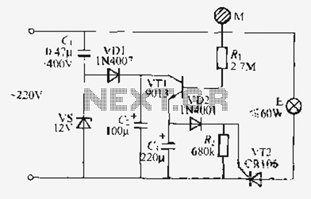
Utilize the call sheet to touch the electrical threshold M, which causes the E lamp to light up. When the same interval subparagraph is triggered, the lights will automatically turn off. A voltage regulator rectifier circuit is formed using...

Computer memory power supply circuit (NCP5201). This circuit illustrates a typical power supply configuration for computer memory, utilizing the NCP5201 power management chip. It features a dual-output design. The NCP5201 is a highly integrated power management solution designed specifically for...
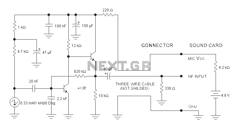
The sound card for a PC typically includes a microphone input, speaker output, and occasionally line inputs and outputs. The microphone input is specifically designed for dynamic microphones, accommodating an impedance range of 200 to 600 ohms. An adaptation...
Oscillation is expected at the resonant frequency where the positive feedback is in phase with the input, specifically at 0 degrees. For oscillation to take place, the gain must be equal to or greater than 1 at that frequency....
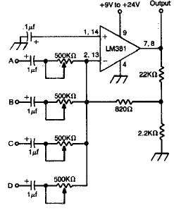
LM381 4-channel audio mixer circuit design project using a few common electronic parts. The LM381 audio mixer circuit is designed to combine audio signals from four separate channels into a single output. This circuit employs the LM381 integrated circuit, which...
Warning: include(partials/cookie-banner.php): Failed to open stream: Permission denied in /var/www/html/nextgr/view-circuit.php on line 713
Warning: include(): Failed opening 'partials/cookie-banner.php' for inclusion (include_path='.:/usr/share/php') in /var/www/html/nextgr/view-circuit.php on line 713