
voltage to frequency converter icl8038
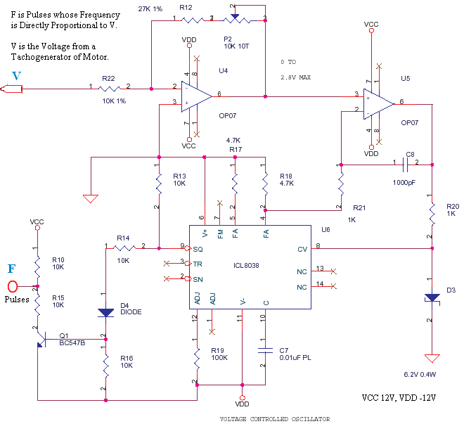
The circuit utilizes the ICL8038 waveform generator, known for its precision in generating sine, square, triangular, and pulse waveforms. In this application, it produces square wave pulses that serve as timing signals for the CD4040 binary counter. The CD4040 is a 12-stage binary ripple counter that can count pulses and is capable of operating from a dual power supply, making it suitable for this configuration.
The tachogenerator provides feedback by generating a voltage proportional to the speed of the motor driving the conveyor. This feedback voltage is essential for monitoring the operational speed and ensuring accurate counting of impacts. The voltage is conditioned through attenuation and filtering to prevent noise from affecting the measurement and to ensure compatibility with the input requirements of the ICL8038.
Resistors R10 through R15 are part of a voltage divider network that ensures the correct voltage levels are maintained for the logic circuitry. The inclusion of transistor Q1 serves to buffer the output, allowing the circuit to drive loads effectively while maintaining the integrity of the pulse signals. The virtual ground concept allows the circuit to operate efficiently in a bipolar supply configuration, ensuring that the logic levels are appropriately referenced.
Overall, this circuit exemplifies a well-integrated design that combines waveform generation, feedback control, and counting mechanisms, making it a robust solution for impact counting applications in industrial settings.This was a small circuit made for driving an Impact counter. The heart being ICL8038. It must have been a Motor driving a Conveyor, the motor has a feedback attachment called Tachogenerator. Only part of the circuit is shown here. See the image of product here Tacho Counter. The configuration is derived from the Application Notes of Intersil. T he Voltage from Tachogenerator is Measured on a DPM-DVM and also fed to this circuit after attenuation and filtering. The square pulses of 8038 is used to derive a Logic pulse train for a CD4040. The CD4040 works of 0 and 12V. The above circuit is on +12 and -12. That is the reason R10-R15-Q1 are used. The pulses are 0-12V pulses. The Zero is Virtual like the Virtual Ground in low current power supplies. 🔗 External reference
Related Circuits
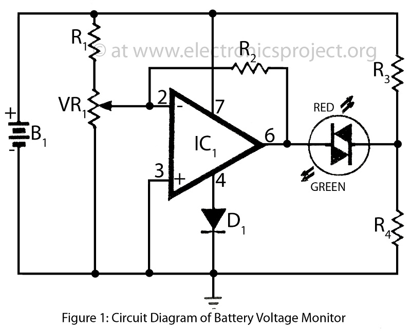
Battery voltage monitor is utilized to indicate the voltage level of a 12-volt battery circuit, specifically in a verified electronics project circuit. The battery voltage monitor circuit is designed to provide a visual representation of the voltage level of a 12-volt...
Frequency measurement is crucial in radio construction, as it allows for the setting of desired frequencies in both receivers and transmitters, as well as monitoring frequency drifts. A frequency counter can verify oscillator functionality and ensure stability in generation....

This device is designed to be a simple, inexpensive comparator intended for use in a solar cell power supply setup where a quick "too low" or "just right" voltage indicator is needed. The circuit consists of one 5V regulator,...
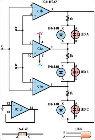
This circuit indicates which of three voltages, ranging from approximately -4V to +4V at points A, B, and C, is the highest by illuminating one of three indicator LEDs. It can also be configured to indicate the lowest of...
The VFC62 is a voltage-to-frequency and frequency-to-voltage converter that effectively transforms analog signals into digital signals. The digital output is presented in an open collector format, where the digital pulse repetition rate is directly proportional to the amplitude of...
The battery voltage is 1V for a low-frequency amplifying circuit, which can operate with a power supply voltage ranging from 1V to 1.7V, making it suitable for use with small batteries. The circuit provides an output power of 80mW...