
SINGLE TRANSISTOR CODE PRACTICE OSCILLATOR

The circuit utilizes a 2N366 transistor, which is a general-purpose NPN transistor, serving as the primary active component in the audio feedback oscillator configuration. The audio transformer plays a crucial role in coupling the output signal back to the input, thereby creating the feedback necessary for oscillation.
In this setup, the audio transformer is connected to the collector of the 2N366, allowing the amplified audio signal to be fed back into the base of the transistor. This feedback mechanism is essential for sustaining oscillations at a frequency determined by the values of the surrounding components, including resistors and capacitors.
The resistor R1 is particularly important as it adjusts the biasing of the transistor. By varying R1, one can control the gain of the circuit and, consequently, the frequency of the audio oscillation. A lower resistance value typically allows for a higher gain, resulting in a higher frequency output, while a higher resistance value reduces the gain and lowers the frequency.
The output of the circuit can be taken from the secondary winding of the audio transformer, which can be connected to a speaker or an audio processing unit, allowing for sound generation. Proper tuning of R1 is critical to achieve the desired audio note, which can be used in various applications such as sound effects, alarms, or as part of a larger audio system.
Overall, this simple yet effective circuit demonstrates the principles of feedback and oscillation in audio applications, showcasing the versatility of the 2N366 transistor in generating sound through electronic means.A 2N366 is configured as an audio feedback oscillator using an audio transformer is shown. Adjust R1 for proper operation and desired audio note.. 🔗 External reference
Related Circuits
The circuit presented is a standard Colpitts oscillator, commonly utilized in many amateur radio homebrew transmitters. This specific circuit is designed to operate effectively within a frequency range of 1500 kHz to 8000 kHz. To accommodate lower frequencies, it...
The circuit was designed to operate a frequency modulation voice transmitter over the FM band within the VHF frequency range. The transmitter is an electronic device. The frequency modulation (FM) voice transmitter circuit operates within the VHF (Very High Frequency)...

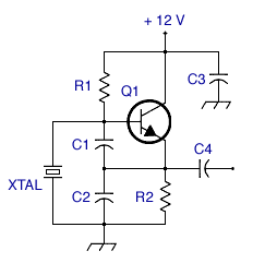
This design schematic illustrates a Crystal Colpitts oscillator that can be implemented using a transistor and a parallel mode crystal. In this circuit, the crystal functions as an inductance. A large value capacitive divider is utilized between the gate,...
This code lock circuit is an electronic combination lock designed for daily use. It only responds to the correct sequence of four digits entered remotely. If an incorrect key is pressed, the lock resets. The lock code can be...
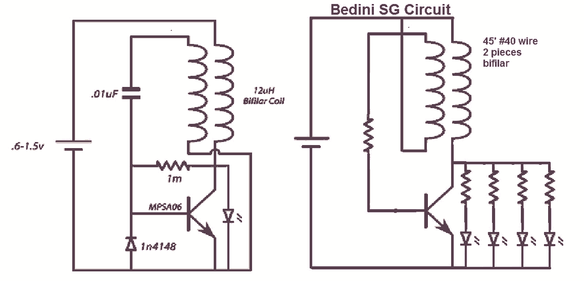
It would be beneficial to obtain schematics of the Joule Thief and Bedini oscillator circuit connections. This is an area that has not been previously explored. The schematic on the left was sourced from the Energetic Forum, while the...
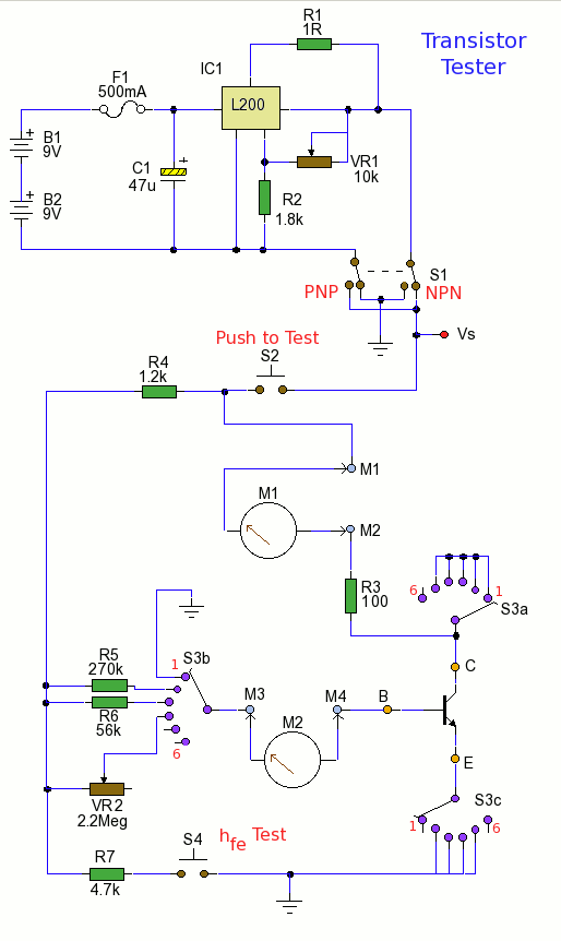
This circuit can measure both small signal hfe and DC current gain hFE of a low to medium power transistor. The circuit is designed to evaluate the current gain characteristics of low to medium power transistors by measuring both the...