
1 transistor treasure locator circuit
PARTS LIST:
- B1 — 9-Vdc transistor battery
- C1 — 365-pF trimmer or variable capacitor
- C2 — 100-pF, 100-V silver mica capacitor
- C3 — 0.05-µF disc capacitor
- C4 — 4.7- or 5-µF, 12-V electrolytic capacitor
- L1 — Search coil consisting of 18 turns of #22 enamel wire, scrambled wound on a 4-inch diameter form
- Q1 — RCA SK3011 npn transistor or equivalent
- R1 — 680-ohm, 1/2-watt resistor
- R2 — 10,000-ohm, 1/2-watt resistor
- R3 — 47,000-ohm, 1/2-watt resistor
The described locator circuit functions as a metal detector, leveraging the principles of inductance and oscillation. The core component of the system is the search coil, L1, which is intricately wound to create a specific inductance value. This inductance is crucial as it interacts with the oscillator circuit to produce a frequency that can be detected by the radio.
The oscillator circuit is comprised of the variable capacitor C1, which allows for fine-tuning of the oscillator frequency to match the detected signal frequency. The radio serves as an auditory output device, providing feedback through changes in tone when metal is detected. The change in frequency occurs because the presence of metal alters the inductance of L1, leading to a shift in the oscillator's output.
The use of RTV adhesive to stabilize the search coil is a critical step in ensuring consistent performance. This adhesive prevents any mechanical movement that could lead to variations in inductance during operation, thereby enhancing the reliability of the locator.
The power supply is provided by a 9-Vdc transistor battery (B1), which powers the entire circuit. The remaining components, including the resistors R1, R2, and R3, serve to set the biasing and gain of the transistor Q1, which is central to the oscillator's operation. Capacitors C2 and C3 filter and stabilize the circuit, ensuring that it operates within the desired frequency range without unwanted noise.
In summary, this locator circuit integrates various electronic components to create a functional metal detection system, utilizing a combination of inductive principles and radio frequency detection to provide real-time feedback on the presence of metallic objects.Locator uses a transistor radio as the de-tector. With the radio tuned to a weak station, adjust Cl so the locator oscillator beats against the received signal. When the search head pas¬ses over metal, the inductance of LI changes thereby changing the locator oscillator's fre¬quency and changing the beat tone in the radio.
The search coil consists of 18 turns of #22 enameled wire scramble wound on a 4-in. diameter form. After the coil is wound and checked for proper operation, saturate the coil with RTV adhesive for stable operation of the locator. PARTS LIST : B1 — 9-Vdc transistor battery C1 —365-pF trimmer or variable capacitor C2—-100-pF, 100-V silver mica capacitor C3—0.05-/i.F, disc capacitor C4—4.7- or 5-^F, 12-V electrolytic capacitor L1—Search coil consisting of 18 turns of #22 enamel wire scramble wound on 4-in. diameter form Q1 — RCA SK3011 npn transistor or equiv. R1 —680-ohm, 1/2-watt resistor R2— 10,000-ohm, V2-watt resistor R3—47,000-ohm, 1/2-watt resistor
🔗 External reference
Related Circuits
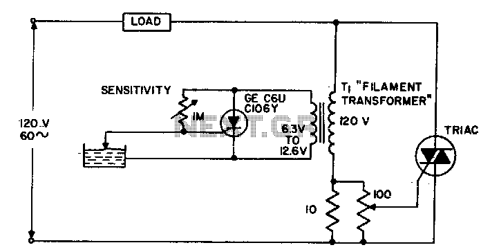
The circuit supplies power to the load until water conducts through the probe, allowing gate current to bypass from the low current SCR. This configuration provides an isolated low voltage probe to meet safety requirements. The described circuit operates as...
The circuit can be constructed using a pair of twin-T oscillators, with the Q factor adjusted to the threshold of oscillation, allowing them to resonate like a bell when activated by a voltage pulse. Each twin-T oscillator is designated...
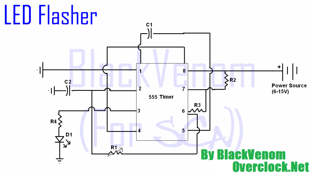
All of the components in this list are generally available through RadioShack for less than $20. It is highly recommended to use a breadboard for assembly, as mistakes are common for first-time builders, and soldering can complicate troubleshooting. This...
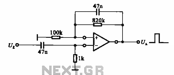
It demonstrates the use of various types of pulse signal generating circuits utilizing operational amplifiers. The circuit described involves the implementation of pulse signal generators using operational amplifiers (op-amps), which are versatile components frequently employed in analog electronics. These circuits...
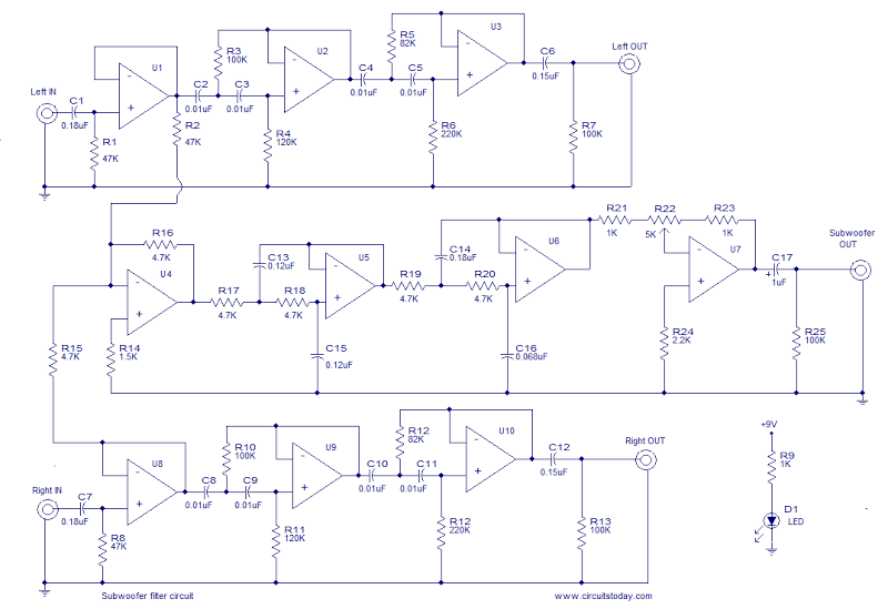
This is the schematic diagram of an operational amplifier (op-amp) based subwoofer filter. Audio frequencies below 200 Hz are typically categorized within the subwoofer range, indicating that a subwoofer filter should have a cutoff frequency around 200 Hz. The...
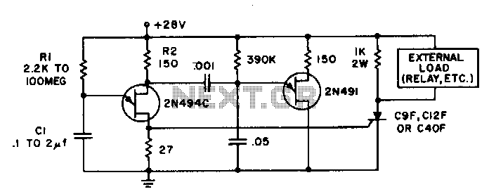
Time delays ranging from 0 milliseconds to over three minutes can be achieved with this circuit without the need for tantalum or electrolytic capacitors. The timing interval begins when power is applied to the circuit. At the conclusion of...