
Pulse signal generating circuit
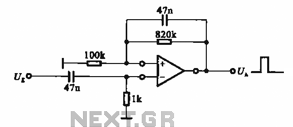
The circuit described involves the implementation of pulse signal generators using operational amplifiers (op-amps), which are versatile components frequently employed in analog electronics. These circuits can generate a variety of pulse waveforms, including square waves, triangular waves, and sawtooth waves, depending on the configuration of the op-amps and associated passive components.
A common configuration for generating a square wave involves the use of a comparator circuit. In this setup, an op-amp is configured with a feedback resistor and a capacitor. The capacitor charges and discharges through the resistor, creating a voltage that oscillates between two thresholds. The output of the op-amp switches states when the input voltage crosses these thresholds, resulting in a square wave output.
For triangular wave generation, an integrator circuit can be constructed using an op-amp. This configuration takes the square wave output from the comparator and integrates it over time, producing a linear ramp up and down, which results in a triangular waveform at the output.
In a sawtooth wave generator configuration, a combination of an integrator and a comparator can be used. The output from the integrator, which ramps up linearly, is fed into a comparator that resets the integrator when it reaches a certain threshold. This creates a sawtooth waveform, characterized by a linear rise followed by a sudden drop.
These pulse signal generating circuits can be adjusted for frequency and amplitude by varying the values of the resistors and capacitors in the circuit. The ability to produce different types of pulse signals makes these circuits valuable in various applications, including signal processing, timing applications, and waveform generation for testing electronic devices. Proper design considerations, including power supply decoupling and component selection, are essential for ensuring stable and reliable operation of these pulse generating circuits.It shows the use of various forms of pulse signal generating circuit operational amplifier.
Related Circuits
A high voltage power supply is a valuable source that can be effectively used in various applications, such as biasing gas-discharge tubes and radiation detectors. This type of power supply can also serve as a protective measure, such as...
The electronic fishing shrimp machine circuit consists of an astable oscillator, an inverter circuit, and a high-voltage output circuit, as depicted in Figure 20. The astable oscillator circuit includes a time-base integrated circuit (IC), resistors R3 and R4, a...
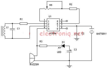
Metal detector schematic circuit using CS209A and a few electronic components. The metal detector circuit utilizing the CS209A integrated circuit is designed to detect metallic objects through the principle of electromagnetic induction. The CS209A is a specialized IC that facilitates...
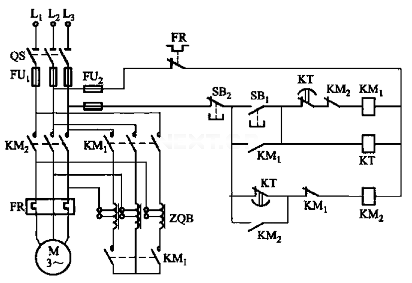
The circuit depicted in Figure 3-49 illustrates an autotransformer that is controlled by a time relay (KT). The delay time set by the KT relay corresponds to the motor's startup duration. The circuit utilizes an autotransformer, which is a type...
The circuit below illustrates generating a single positive pulse which is delayed relative to the trigger input time. The circuit is similar to the one above but employs two stages so that both the pulse width and delay can...
This simple-to-construct water fishing thermometer circuit is intended for use in sports applications, such as fishing contests. A sensor measures... This water fishing thermometer circuit is designed to provide accurate temperature readings of water, making it an essential tool for...
Warning: include(partials/cookie-banner.php): Failed to open stream: Permission denied in /var/www/html/nextgr/view-circuit.php on line 713
Warning: include(): Failed opening 'partials/cookie-banner.php' for inclusion (include_path='.:/usr/share/php') in /var/www/html/nextgr/view-circuit.php on line 713