
555 Timer LED Flasher Circuit
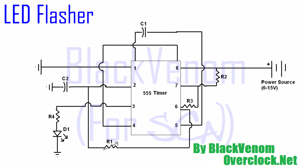
The described circuit involves several components that work together to create a functional electronic project. The power supply, which can range from 6V to 15V, is crucial for providing the necessary voltage to drive the circuit. AA batteries are a convenient option, but a proper power supply unit (PSU) can also be employed. The inclusion of resistors, specifically two 1K ohm resistors and one 100 ohm resistor, serves to limit current and protect sensitive components, ensuring safe operation.
Capacitors play a vital role in this circuit, with a 0.1uF capacitor used for decoupling and a variable 470uF capacitor that can be adjusted to modify timing or filtering characteristics. The 10K ohm potentiometer allows for user interaction, providing a means to adjust parameters such as pulse width or frequency in the circuit.
The 555 timer IC is a versatile component that can be configured in various modes, including astable and monostable configurations. In this application, it is likely used in an astable mode to generate a square wave output that can drive other components such as LEDs or the CD-ROM motor.
The circuit can be built on a breadboard, which is ideal for prototyping and testing. The use of 22-26 gauge wire facilitates connections between components, while soldering is reserved for final assembly once the design has been verified on the breadboard. A project box can be utilized for housing the completed circuit, and a switch is incorporated to control power to the circuit.
The innovative concept of using a CD-ROM drive motor introduces an interesting application of the circuit. By wiring the motor terminals in series and controlling them with the output from the 555 timer, the circuit can potentially create a sequencer effect, where the motor's speed is modulated by the pulse rate adjusted via the potentiometer. This adds a dynamic element to the project, showcasing the versatility of the components used.All of the parts in this list are generally available through Radioshack for less than $20. I highly recommend using breadboard! You`re bound to make mistakes your first time and soldering it will only make your fail worse (double fail ). I`ve compiled this tutorial into two "methods", one is the classic schematic and the other is a step by step g
uide. Also, if you`re new to electronics read through this post before you make the circuit. - 6-15V (AA, or correct PSU)* - 2 1K ohm resistors - 1 100 ohm resistor - 1. 01uF capacitor - 1 470uF capacitor (variable) - 1 10K ohm potentiometer (optional) - 1 555 IC Linear Timer - X LEDs (it`s up to you, IR <=6) - 22-26g wire - pc board (breadboard for testing) - solder & iron - project box (optional) - switch (goes before circuit on + wire) *If you go less than 12v and you intend to use this in your car you need to compensate for the extra voltage that will be going to the circuit. Oh, I got a genius idea. To make an old CD-rom drive spinner motor work, you have to fire all the wires in series around the motor.
So, what you could do is take a 555 and a decade counter and make an LED sequencer circuit. Then instead of wiring it to LED`s, wire it to each terminal on the CD-rom motor. I would be sure to use the POT to adjust the pulse rate, thus motor speed. This is only a theory, but if one of you try it, post results. I may try it myself. 🔗 External reference
Related Circuits
The circuit is presented, consisting of a language and sound circuit FM transmitter. It is simple and easy to manufacture, compatible with ordinary FM radios, allowing for potential listening scenarios and preventive measures. The FM transmitter circuit is designed to...
The timing circuit utilizes an electronic switch composed of F1, F2, and VT1 to reduce quiescent current to approximately 1 to 2 A with the 555 timer. Upon initial power-up, the voltage across capacitor C2 cannot instantly change, causing...
The objective is to enhance information transmission through the distribution of articles. For any issues related to article content, copyright, or other concerns, please contact us via email at [email protected] within 15 days. Prompt action will be taken to...
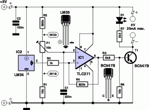
This circuit illustrates the TDA1054 tone control stereo preamplifier circuit diagram. Features include the National Semiconductor LM35 integrated circuit, which utilizes semiconductor technology. The TDA1054 is a versatile integrated circuit designed for use in audio applications, particularly in tone control...
In a complete circuit, there are two types of elements: active and passive elements. Active elements generate energy, while passive elements dissipate energy. Examples of passive elements include resistors and capacitors. In electronic circuits, active and passive components serve distinct...
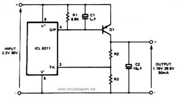
The IC8211 serves as a voltage reference and regulator amplifier, with Q1 likely functioning as the series pass transistor. R1 determines the output current of the IC8211, while C1 and C2 contribute to loop stability and help suppress the...
Warning: include(partials/cookie-banner.php): Failed to open stream: Permission denied in /var/www/html/nextgr/view-circuit.php on line 713
Warning: include(): Failed opening 'partials/cookie-banner.php' for inclusion (include_path='.:/usr/share/php') in /var/www/html/nextgr/view-circuit.php on line 713