
1 watt four stage FM transmitter circuit with 2n2219 BF494 BF200 and 2N3866
This FM transmitter circuit is designed for the transmission of audio signals over a short range utilizing frequency modulation. The circuit architecture includes a VHF oscillator, which is crucial for generating the carrier frequency, and operates effectively with the BF494 transistor. The oscillator's output is frequency-modulated by the audio input from the condenser microphone, which captures sound waves and converts them into electrical signals.
The preamplifier stage, utilizing the BF200 transistor, boosts the weak audio signals from the microphone to a sufficient level for further processing. This stage is vital for ensuring that the subsequent driver stage receives a strong enough signal to produce a high-quality output.
The driver stage, implemented with the 2N2219 transistor or the alternative 2N5109, plays a critical role in preparing the signal for amplification. Operating in class-C mode, it efficiently amplifies the RF signal while minimizing distortion, making it suitable for radio frequency applications.
The final amplification stage employs the 2N3866 transistor, which is a power amplifier capable of delivering up to 1 watt of RF power. The use of a heat sink is essential for this component to dissipate heat generated during operation, thereby preventing thermal overload. The output is designed to connect to a 50-ohm antenna, which can be either a dipole or a ground plane, ensuring effective radiation of the RF signals.
The circuit's tunability is facilitated by the trimmers VC1 to VC7, which allow for fine adjustments to achieve the desired frequency range of 88-108 MHz. This frequency range is standard for FM broadcasting, making the circuit suitable for personal or experimental use.
The inclusion of a voltage regulator IC 78C09 ensures that the oscillator receives a stable voltage supply, which is critical for maintaining consistent frequency output. This feature enhances the reliability of the transmitter, especially in environments where supply voltage may fluctuate.
The construction of coils L1 through L5 with specified turns and wire gauge is critical for achieving the desired inductance values, which directly impact the tuning and performance of the circuit. Each coil's design is tailored to optimize the circuit's performance across the intended frequency range.
Overall, this FM transmitter circuit represents a well-structured approach to audio transmission, combining various stages of amplification and modulation to achieve effective short-range communication. Proper assembly and tuning are essential for maximizing performance and ensuring compliance with regulatory standards for FM transmission.This FM transmitter circuit uses four radio abundance stages: a VHF oscillator congenital about transistor BF494 (T1), a preamplifier congenital about transistor BF200 (T2), a disciplinarian congenital about transistor 2N2219 (T3) and a ability amplifier congenital about transistor 2N3866 (T4). A condenser microphone is affiliated at the ascribe o f the oscillator. Working of the 1 Watt transmitter ambit is simple. When you allege abreast the microphone, frequency-modulated signals are acquired at the beneficiary of oscillator transistor T1. The FM signals are amplified by the VHF preamplifier and the pre-driver stage. You can additionally use transistor 2N5109 in abode of 2N2219. The preamplifier is a acquainted class-A RF amplifier and the disciplinarian is a class-C amplifier. Signals are assuredly fed to the class-C RF ability amplifier, which delivers RF ability to a 50-ohm accumbent dipole or arena even antenna.
Use a heat-sink with transistor 2N3866 for calefaction amusement (Note: or 2N4427 because it works bigger at 12 V and delivers up to 1 watt RF power). Carefully acclimatize trimmer VC1 affiliated beyond L1 to accomplish abundance aural 88-108 MHz. Additionally acclimatize trimmers VC2 through VC7 to get best achievement at best range. Regulator IC 78C09 provides abiding 9V accumulation to the oscillator, so aberration in the accumulation voltage will not affect the abundance generated.
You can additionally use a 12V array to ability the circuit. Assemble the ambit on a accepted purpose PCB. Install the antenna appropriately for best range. Coils L1 through L5 are fabricated with 20 SWG copper-enameled wire anguish over air-cores accepting 8mm diameter. They accept 4, 6, 6, 5 and 7 turns of wire, respectively. 🔗 External reference
Related Circuits
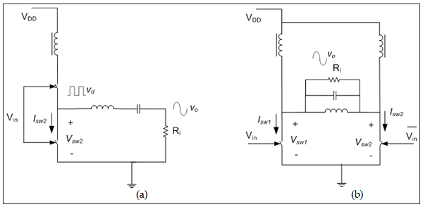
The measured output power and efficiency of a 6 dBm 130nm CMOS class-D inverter chain was analyzed, utilizing gate bias variation to generate a pulse width modulated inverter output voltage (Cijvat et al., 2008). Efficiency versus output power was...
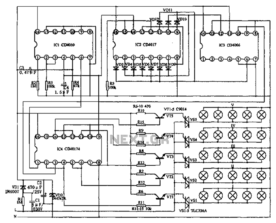
The circuit primarily consists of the NAND gate IC1 (CD4096), a counting/timing distribution circuit IC2 (CD4017), an analog electronic switch IC3 (CD4066), and a D flip-flop IC4 (CD40174), along with other components. The controller is capable of managing the...
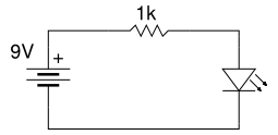
Beginner's Tutorial 1: Building a Circuit on Breadboard - how to build a simple and easy circuit on a breadboard for beginners in electronics. Learn to use an LED and a resistor. This tutorial serves as an introductory guide for...
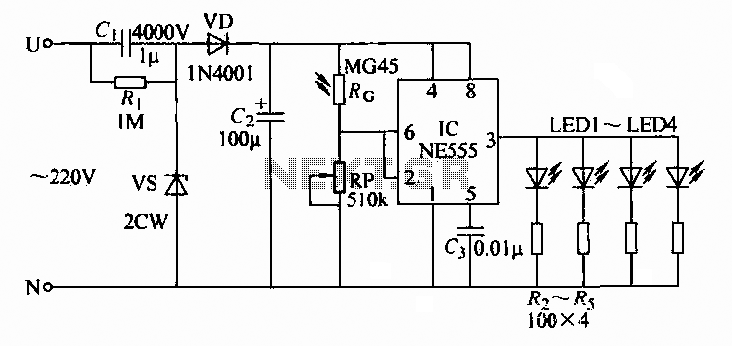
A 220V AC input is converted to a DC operating voltage of approximately 3.3V using a capacitive G buck regulator, a rectifier diode (VD), and a filter capacitor connected to an NE555 integrated circuit (IC). The IC functions as...
A DIY GSM jammer schematic diagram designed specifically for GSM1900 frequencies ranging from 1930 MHz to 1990 MHz. The GSM1900 mobile phone network is utilized in the USA, Canada, and most South American countries. This cell phone jammer is...
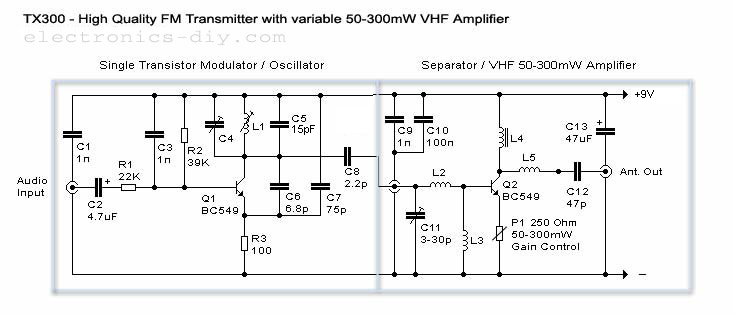
50-300mW FM Transmitter with TX300 Electronic Circuit Schematic Wiring Diagram. The FM transmitter circuit is designed to operate within a power range of 50 to 300 milliwatts, making it suitable for various applications such as amateur radio broadcasting and low-power...