
50-300mW FM Transmitter With TX300
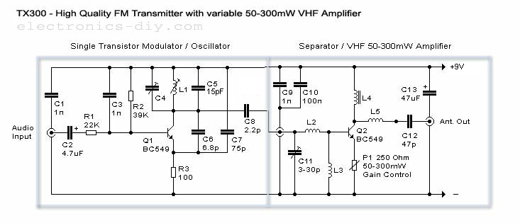
The FM transmitter circuit is designed to operate within a power range of 50 to 300 milliwatts, making it suitable for various applications such as amateur radio broadcasting and low-power audio transmission. The core of the circuit utilizes the TX300 integrated circuit, which is specifically designed for FM transmission tasks.
The schematic typically includes essential components such as a power supply, audio input stage, modulation circuit, and an output stage for RF amplification. The power supply section is responsible for providing a stable voltage to the circuit, often derived from a battery or a regulated power source.
The audio input stage may consist of capacitive coupling to filter out DC components, allowing only the audio signal to pass through. This audio signal is then fed into the modulation circuit, where it is mixed with a carrier frequency generated by an oscillator circuit within the TX300. The modulation process alters the amplitude of the carrier wave based on the audio input, producing an FM signal.
Following modulation, the RF output stage amplifies the modulated signal to the desired power level, ensuring effective transmission over a specific range. Antenna matching components may also be included to optimize the output for the antenna, enhancing transmission efficiency.
Overall, this FM transmitter circuit is designed for simplicity and effectiveness, making it accessible for hobbyists and engineers looking to explore FM transmission technology.50-300mW FM Transmitter With TX300 Electronic Circuit Schematic Wiring Diagram. 🔗 External reference
Related Circuits
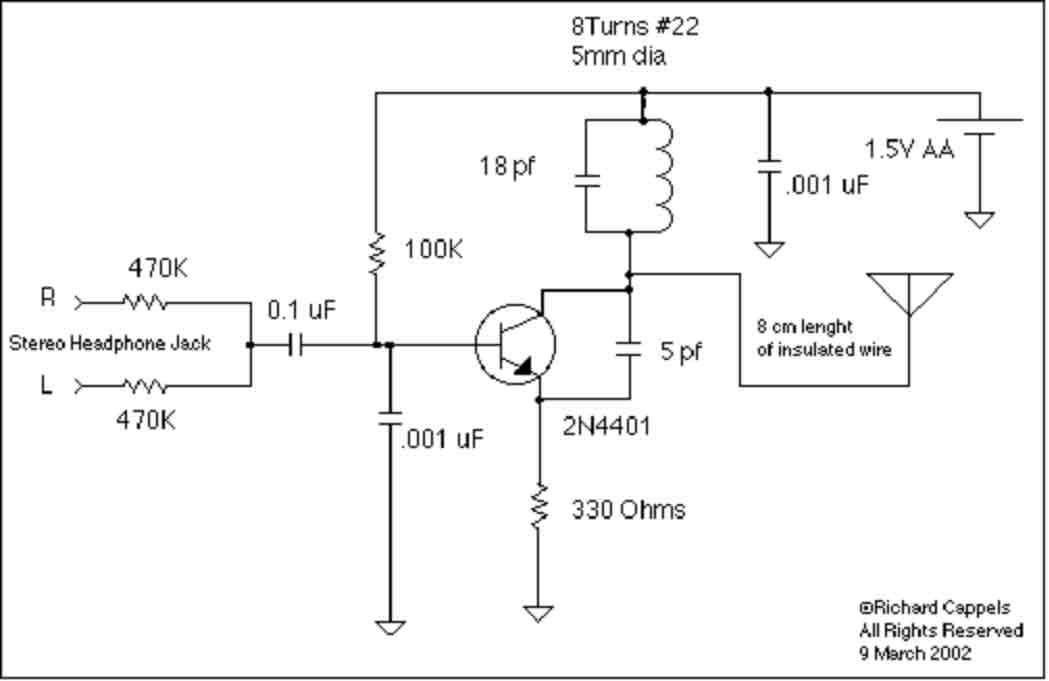
This implementation is adapted to rebroadcast the output of a CD player, television receiver, or radio receiver. I use it so that I can move about the house and listen to my favorite programs without disturbing others. Within the...
This is a small but quite powerful FM transmitter having three RF stages incorporating an audio preamplifier for better modulation. It has an output power of 4 Watts and works off 12-18 VDC which makes it easily portable. It...
User Agreement & Disclaimer Disclaimer All files are found using legitimate search engine techniques. This site does not and will not condone hacking into sites to create the links it lists. It is assumed that all links found on...
This transmitter is highly stable and can deliver up to seven watts of power using the specified components and tubes. The use of valves should not deter users, as they are straightforward to work with, and many valves can...
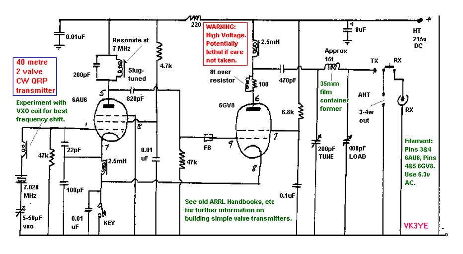
This is a 40 meter transmitter which uses two valves, the 6AU6 and 6GV8. The construction is easy. Just be careful due to high voltage present. More: Experiment with VXO coil for best frequency shift. See old ARRL Handbooks...
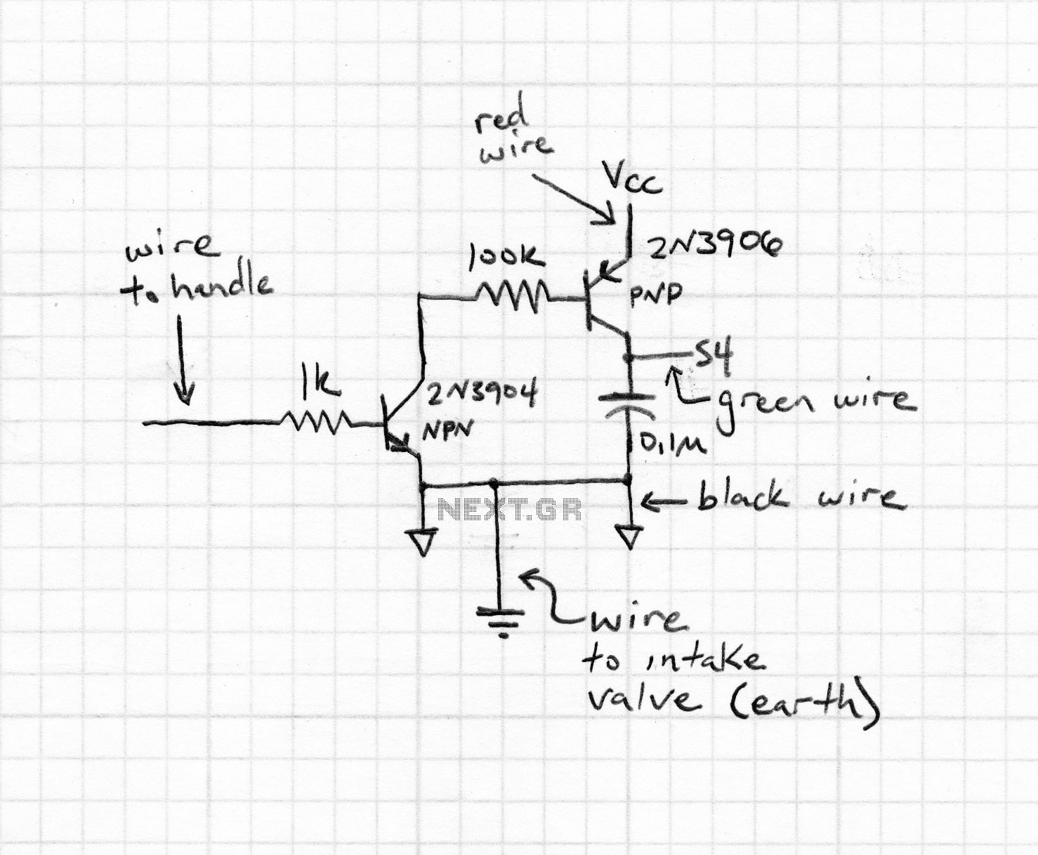
This compact transmitter employs a Hartley oscillator configuration. Typically, the capacitor in the tank circuit connects to the base of the transistor; however, at VHF frequencies, the base-emitter capacitance of the transistor behaves like a short circuit, maintaining its...