
Lantern controller circuit diagram of a two-dimensional
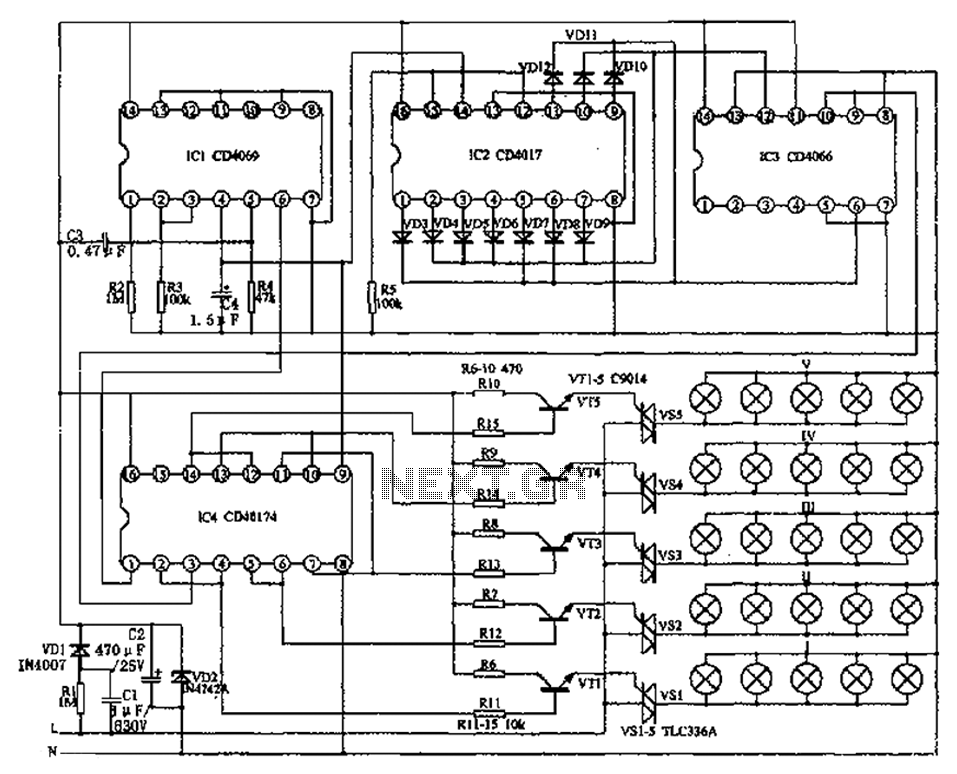
The described circuit utilizes several integrated circuits to achieve a dynamic lighting effect suitable for decorative or signaling purposes. The NAND gate (IC1, CD4096) serves as the fundamental logic component, enabling the configuration of various logical operations necessary for controlling the overall functionality of the circuit. This IC can be used to create necessary timing signals or control conditions for the subsequent components.
The CD4017 (IC2) functions as a decade counter and timing distribution circuit, which counts incoming pulses and activates its output pins sequentially. This feature is essential for the progressive lighting effect, as it allows the lanterns to be lit one after another, creating a visually appealing sequence. The outputs of the CD4017 can be connected to the analog electronic switch (IC3, CD4066), which controls the power to each lantern. The CD4066 operates as an analog switch, allowing or blocking current flow based on control signals, thus enabling the sequential activation of the lanterns.
The D flip-flop (IC4, CD40174) is utilized for storing the state of the control signals, ensuring that the circuit maintains its operational state even when the input signals fluctuate. This stability is crucial for maintaining consistent lighting patterns and ensuring that the lanterns do not flicker or behave erratically.
Additionally, the circuit design allows for the integration of multiple light connections, which enhances the ability to create color-changing scenes. By utilizing different colored LEDs or lanterns, the system can produce a flowing color effect that is richer and more varied than traditional single-color setups. This capability is particularly beneficial for decorative applications, where visual impact is a priority.
Overall, the combination of these integrated circuits and their respective functionalities creates a sophisticated control system for lantern lighting, allowing for intricate patterns and effects that enhance the aesthetic appeal of any installation. As shown, mainly by the NAND gate IC1 (CD4096), counting/timing distribution circuit IC2 (CD4017), the analog electronic switch IC3 (CD4066) and the D flip-flop IC4 (CD40174) a nd other components. The controller may control Lantern Rd progressive increments lit lantern in the progressive extinguished. If a certain number of lights connections, the plane will be able to create a color-changing scene, color flow control than usual in a line of colorful richer.
Related Circuits
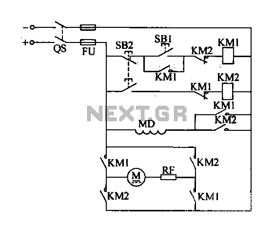
A DC motor reverse brake circuit is presented. To initiate braking, the stop button (SB2) is pressed, which disconnects the move-off contact, causing KM1 to lose power and release. Subsequently, the brake contactor (KM2) is activated. KM2 is designed...
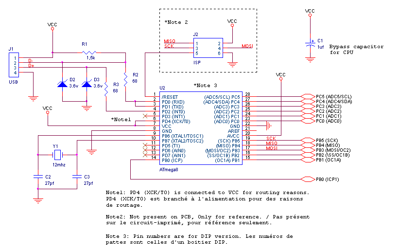
This project allows the use of Sega Saturn peripherals (controllers, mouse) on a PC via a USB port. By utilizing the schematic and firmware available on this page, an adapter can be created using the connector from a Saturn...
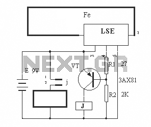
The circuit operation principle of the device illustrated in the figure is as follows: When the barbed wire is intact, the output pin of the LSE is high due to the absence of contact. Consequently, the transistor VT is...
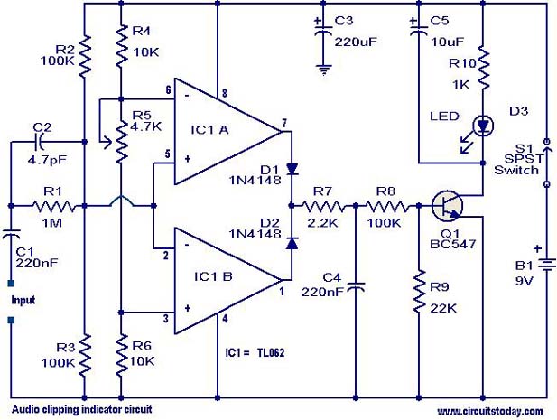
This circuit is designed to detect clipping in a specific waveform. Clipping occurs when the amplitude of a waveform decreases before reaching its expected limit. The circuit activates an LED as an indication that the tested signal is experiencing...
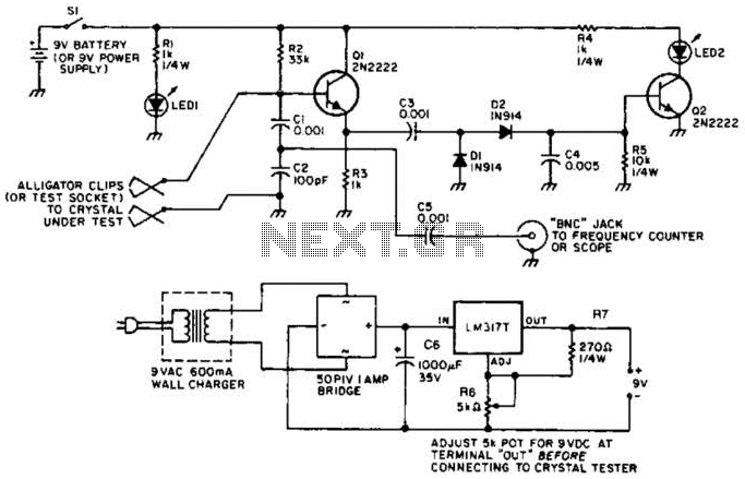
Q1 functions as a Colpitts crystal oscillator. If the crystal being tested is operational, the RF signal is rectified by diodes D1 and D2, which activates Q2 and illuminates indicator LED2. Additionally, LED1 serves as a power indicator. The circuit...
This circuit utilizes two operational amplifiers (op-amps) to create a unique sound effect. The first op-amp, CA741, is configured as a standard astable multivibrator, generating timing pulses controlled by components C1, R2, and variable resistor VR1. The output from...