
1 watt PLL portable fm transmitter circuit
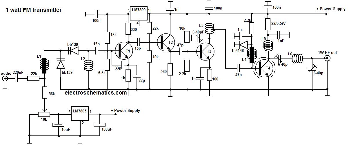
This portable FM transmitter is designed for ease of use and efficient performance in transmitting audio signals over FM frequencies. The integration of a limiter ensures that the audio signal remains within acceptable amplitude levels, preventing distortion during transmission. The microphone amplifier allows for direct input of audio signals, making it suitable for various applications, including personal broadcasting and educational demonstrations.
The PLL (Phase-Locked Loop) section is crucial for maintaining frequency stability and accuracy. By allowing for digital tuning, it simplifies the process of selecting the desired transmission frequency. The division of the schematic into three distinct sections facilitates troubleshooting and understanding of the circuit's operation. The RF section handles the modulation and amplification of the radio frequency signal, while the audio section processes the input audio signal.
To operate the transmitter effectively, the user must connect a 6 V / 0.1 A bulb to provide visual feedback of the RF power output. By setting the RF power to high, the transmitter is activated, and tuning must be performed on a receiver to ensure proper reception of the transmitted signal. Adjustments to the L1 coils may be necessary to achieve optimal tuning, and the position of L1 should be fixed when the tuning voltage at Q3 falls within the specified range of 4-9 V.
Capacitors C15, C16, and C17 play a vital role in fine-tuning the transmitter's output power. Their values can be adjusted to maximize the brightness of the bulb, indicating the highest power output achievable. The final steps involve connecting an appropriate antenna and audio source, with resistor R1 being adjusted to balance the audio output level, ensuring it matches the loudness of other stations. This careful calibration allows for a clear and effective transmission of audio signals over FM frequencies.This Simple Portable FM transmitter includes a limiter, a microphone amplifier and a PLL digital tuning. All the components are placed on one circuit board. The RF power is switchable between 1 W (HI) and 0, 2 W (LO). The schematic diagram is split into 3 parts: RF part (numbered from 1), PLL (numbered from 30) and audio part (numbered from 50).
Co nnect a 6 V / 0, 1 A bulb to the output and set the correct frequency on PLL. Set the RF power to HI. currently activate the transmitter. you must tune it on a receiver. perhaps you may stretch coils of the L1. Fix the L1 in position when the tuning voltage (on Q3) is in range 4-9 V. Then use C15, C16 and C17 to regulate the best power (the highest light of the bulb). Then you`ll be able to connect antenna and audio signal. change R1 till the audio sounds as loud because the alternative stations. 🔗 External reference
Related Circuits
The simplest method of detecting metal is through a beat frequency oscillator. The circuit consists of two balanced oscillators: one serves as the detector element while the other provides a reference signal. The reference oscillator frequency is set to...
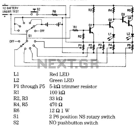
The battery tester utilizes four transistors and two LEDs to indicate the status of any battery being tested. Transistors Q3 and Q4 are configured in a Darlington arrangement, providing extremely high gain. LED L2 illuminates when a small positive...
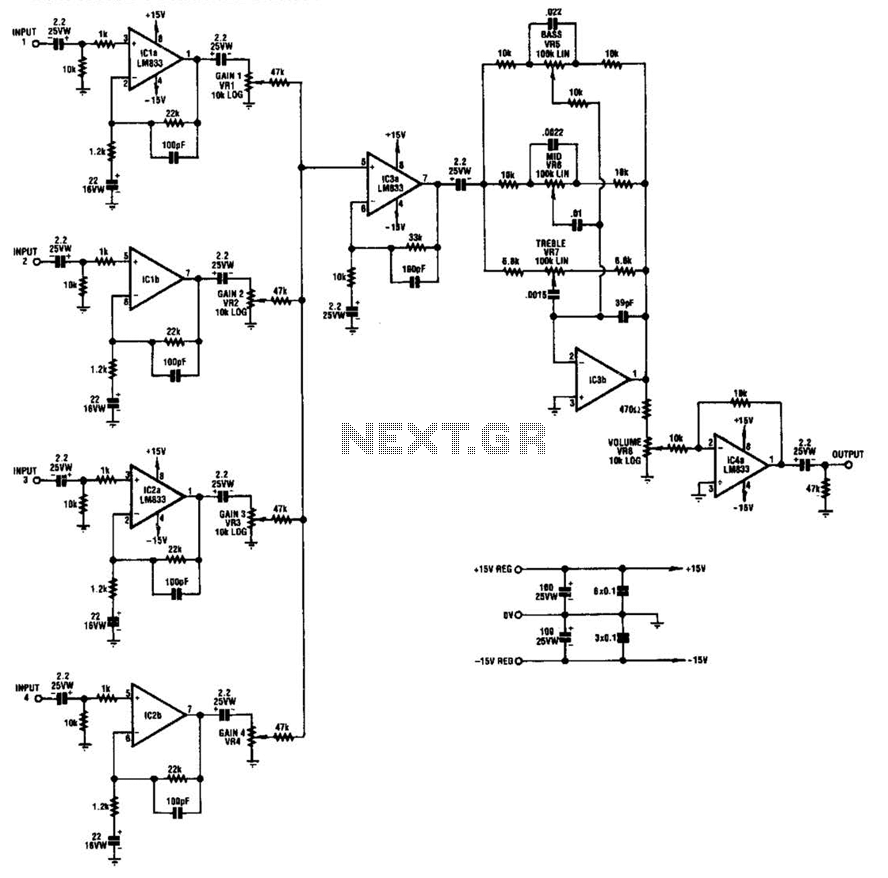
IC1-a, IC1-b, IC2-a, and IC2-b all operate with a gain of approximately 19. Their outputs are combined through level-control potentiometers, and the resulting signal is amplified by IC3-a before being sent to the tone-control stage IC3-b. Finally, the output...
You will need to go to extremes with the heatsink (fan cooling is highly recommended). It was originally intended for "light" intermittent duty, suitable for an equalised subwoofer system (for example using the ELF principle - see the Project...

This circuit is designed for tone control utilizing a three-band equalizer. It is based on the LF351 single-chip operational amplifiers. The circuit features three adjustable ranges: bass, mid, and treble controls. The equalizer allows for approximately +/-20 dB of...
This circuit generates dual-tone bell ringing similar to most doorbell units. It can be used in various applications beyond just doorbells. Several options will be provided in the notes to accommodate different needs. The circuit, as depicted in the...