
Battery Tester Circuit

More: L1 is a red LED, L2 is a green LED, P1 through P5 are 5-kohm trimmer resistors, R1 is 100 kohm, R2 and R3 are 33 kohm, R4 and R5 are 470 ohm, R6 is 12 ohm 1 W, S1 is a 2 P6 position NS rotary switch, and S2 is a normally open pushbutton switch. Depending on the position of S1, a specific trimmer resistor (wiper lead) is selected. This lead connects through the contact on S1 to resistor R1 and into the base of NPN transistor Q1. If the battery is sufficiently charged, a positive voltage reaches the base of Q1, activating it. This action turns Q2 off, allowing Q3 to turn on, which consequently activates Q4 and lights the green LED L2. Conversely, if the battery is weak, Q1 will not activate, causing Q2 to be biased on by R3, which in turn illuminates the red LED L1. When Q1 is on, it biases the base of Q3 negatively, switching Q3 off and preventing L2 from lighting. The circuit functions similarly across all ranges except for the first two, where a 9-V battery is added by S1 in series with the input voltage to facilitate testing of low-voltage batteries. This is necessary because at voltages below 2 VDC, LEDs will not illuminate, and the circuit would fail to indicate a low-voltage (2-V) battery without the additional internal battery voltage. A load resistor is also incorporated, allowing the battery under test to be connected to a load for a more accurate assessment of its condition. This load resistor connects across the battery when the normally open (NO) switch S2 is pressed. The battery tester uses four transistors and two LEDs to indicate the condition of any battery you want to test. Q3 and Q4 are connected in a Darlington configuration that has extremely high gain. LED L2 lights when a small positive potential appears on the base of Q3. Transistors Ql and Q2 form a direct-coupled dc-amplifier circuit. The output of this stage drives the red LED LI. Rotary switch SI is used to select different ranges (which have been previously set by adjusting trimmer resistors PI through P5).The positive (+) lead goes through the selected contacts of SI to the biasing resistors R3, R4, and R5.
The negative (-) lead of the battery under test goes to the ground or common lead of the circuit and the (+) side to one side of PI through P5. LI Red LED,L2 Green LED,PI through P5 5-kohm trimmer resistor,Rl 100 kohm,R2, R3 33 kohm,R4, R5 470ohm,R6 12 1 W,S1 2 P6 position NS rotary switch,S2 NO pushbutton switchDepending on the position of SI, a particular trimmer resistor (wiper lead) is selected. That lead goes through the contact on SI to resistor Rl and into the base of npn transistor Ql. If the battery is good enough, (+) voltage goes to the base of Ql, turning it on. This turns Q2 off, which then allows Q3 to turn on. That causes Q4 to turn on and light green LED L2.If the battery is weak, Ql will not turn on, which will cause Q2 to be biased on by R3, which in turn lights red LED LI.
When Ql is on, it biases the base of Q3 negative, and causes Q3 to be turned off. That prevents L2 from turning on.The circuit operates in the same manner for all ranges except the first two, where a 9-V battery has been added by SI to be in series with the input voltage to allow for testing of very low voltage batteries. That is because at voltages below 2 Vdc, LEDs will not light and the circuit would be unable to set a low-voltage (2-V) battery without the additional internal-battery voltage.
A load resistor has also been included; it allows the battery under test to be connected to a load to give a better indication of its condition. That load resistor is connected across the battery when normally open (NO) switch S2 is depressed. 🔗 External reference
Related Circuits
This design integrates power-on and low-battery indication features, capable of operating with any battery voltage up to 15V. It exhibits a very low current drain of 2mA or less. The circuit design incorporates a power-on indicator that activates when the...

This approach utilizes a Hip-Hop, a shift register, and two gates (A). Before the one-shot pulse, the output of the NOR gate is 0. Consequently, the data input of the D-type flip-flop is equivalent to the trigger. When a...
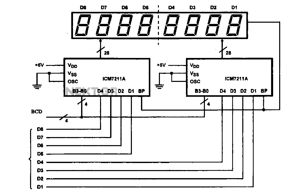
This circuit illustrates an 8-digit digital tube display driver, utilizing two ICM7211A integrated circuits. A BCD (Binary-Coded Decimal) to binary data signal is transmitted to the BO-B3 pins of the ICM7211A. The digital signals are divided into two groups...
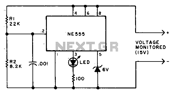
Due to the low duty cycle of the flashing LED, the average current drain is 1 mA or less. The NE555 will trigger the LED when the monitored voltage falls to 12 volts. The ratio of R1 to R2...
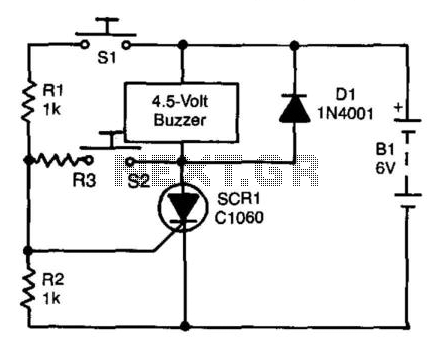
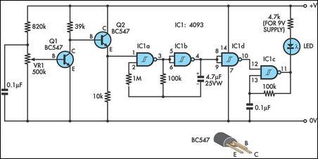
A self-interrupting device connected to a voltage source operates as a switch that continuously opens and closes; thus, the circuit does not latch in the conventional manner, allowing the alarm to function only while switch SI is closed. Due...
Frequently, there are situations where the need arises to utilize a Zener diode, yet the operational voltage is unknown. Often, the characteristics or type inscribed on the diode are not legible. Zener diodes are essential components in electronic circuits, primarily...