
Metal Detector Circuit Schematic using Beat Frequency Oscillator (BFO)
A simple metal detector circuit can be illustrated, where the reference circuit is a basic RC circuit, and its frequency is determined by R1, P2, and C1. The detector oscillator is an LC oscillator, with its frequency determined by the values of L1, C2, and C3. The NAND gates utilized in the circuit are from the CMOS 4011 chip, a low-power component suitable for battery operation. This chip is powered by a 5V voltage supplied from an LM7805L regulator. The regulator's purpose is to maintain a constant voltage source for frequency stability in the reference oscillator, as frequency can be affected by variations in power supply voltage, particularly as the battery voltage decreases over time.
To tune the circuit, a headphone should be connected to the output. With no metal present around the inductor L1, the volume control P1 should be set to the center position, and the reference oscillator tuner P2 adjusted to its maximum or minimum position, resulting in no sound since the frequency will be in the ultrasonic range. Gradually turning P2 will produce a high audio frequency, which will decrease until the note disappears (the frequency dropping below 20 Hz). After tuning, testing the circuit with metal placed near inductor L1 will yield an audible frequency as a detection alert.
The circuit design emphasizes the importance of the inductor-capacitor topology for the detector oscillator, leveraging the inductive response to nearby metallic objects. The use of a CMOS 4011 chip ensures low power consumption, making the circuit practical for portable applications powered by a 9V battery. The LM7805L regulator assists in maintaining operational stability, which is crucial for accurate metal detection, especially in varying battery conditions. The tuning procedure is essential for optimizing the circuit's sensitivity and ensuring reliable detection of metal objects, making this design effective for hobbyists and practical applications alike.The simplest method of detecting metal is by beat frequency oscillator. The circuit basically consists of two balanced oscillator. One acts as the detector element, the other provides the reference signal. This oscillator frequency reference is set to fix value, whilst the detector oscillator varies depending on the metal presence. The reference o scillator can be constructed using various circuit topology: inductor-capacitor (LC), resistor-capacitor (RC), or even a crystal (quartz) oscillator. While the reference oscillator can be implemented using various circuit topology, the detector oscillator always use inductor-capacitor topology, because the mechanism will be using the magnetic induction property of the detected object, and the inductor component of the detector oscillator will be the detecting probe.
With the absence of a metal near the detector probe (the inductor component of the detector oscillator), the detector oscillator is tuned to have same frequency as the reference oscillator. The output of the detector oscillator and the reference oscillator output is mixed using hetero-dyne mixer circuit, producing a beat frequency output of zero Hz, or a very low frequency if both oscillator is slightly unbalanced.
In the presence of a metal near the detector probe, the detector oscillator will shift it`s frequency, and the mixer output will produce a tone with frequency equal to the difference of the reference and the detector frequency. The figure below shows one of the simple metal detector circuit. You can see the reference circuit is a simple RC circuit, and its frequency is determined by R1-P2-C1.
The detector oscillator is an LC oscillator with the frequency is determined by the L1-C2-C3 values. The NAND gates use CMOS 4011 chip, a low power component that is suitable for this battery-operated circuit. You can see that this chip is supplied by a 5V voltage coming from an LM7805L regulator. You might wonder what the purpose of this regulation is, since the power supply come from a 9V battery and the CMOS gates can handle the voltage of 3-15 Volt.
The main purpose of the regulator is to keep a constant voltage source for the reference oscillator frequency stability, since the frequency is affected by the power supply voltage variation as the battery voltage drops in the long time of usage. To tune the circuit, plug a headphone at the output, and remove any metal around the inductor L1. Set the volume control P1 around at center. Set the reference oscillator tuner P2 at the maximum or minimum position, you should hear no sound since the frequency should be in ultrasonic range.
Turn slowly P2 until you hear a very high audio frequency, continue turning the pot until the frequency is decreasing and stop turning when the note is just disappeared (the frequency is decreased down below 20 Hz). After this, you can test the circuit by placing a metal near the inductor L1 and now the output will give an audible frequency as the detection alert.
[Circuit schematic diagram source: hobby-hour. com] 🔗 External reference
Related Circuits
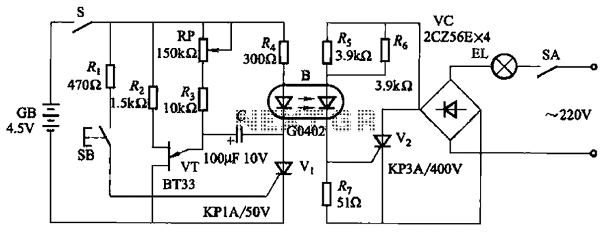
The circuit illustrated in Figure 2-48 consists of two configurations. Configuration 2-48 (a) operates using a 4.5V battery, while configuration 2-48 (b) employs AC capacitors to reduce the voltage supply. In configuration 2-48 (a), the delay time is influenced...

In applications requiring long-range operation with infrared (IR) light sources and high system reliability, pulsed-mode operation of the IR source is essential. Enhanced operational reliability is achieved through synchronous detection of the photodetector current, as implemented in this circuit....
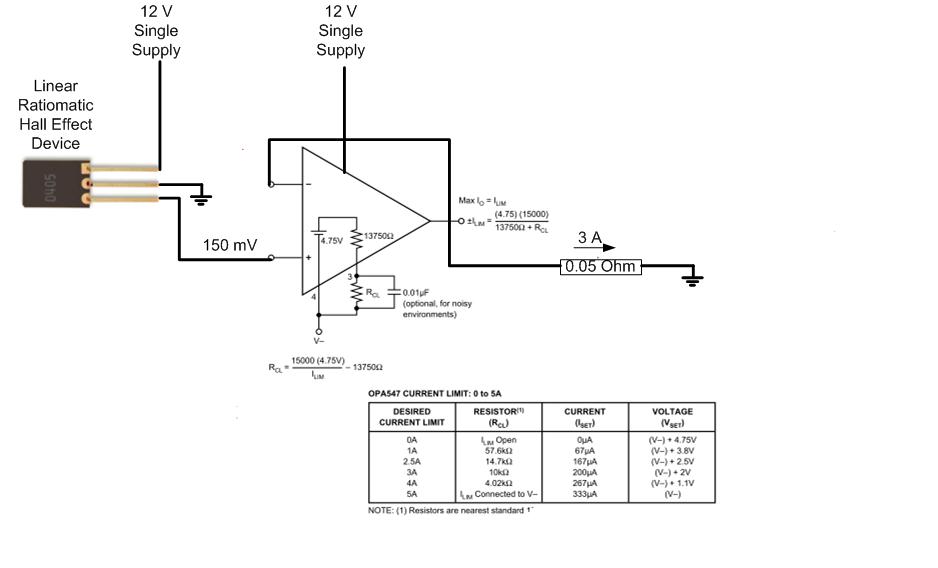
The proposed approach would dissipate (12V)(3A) = 36 watts, which results in significant heat generation in the circuit. This necessitates consideration of two alternatives: 1) Operating the op-amp at a lower supply voltage, if feasible, or 2) Utilizing a...

A digital temperature sensor circuit is explained with a circuit diagram. ICs ADC 0804, LM35, and LM317 are used in this digital circuit project. The digital temperature sensor circuit utilizes three primary integrated circuits (ICs): the ADC 0804, LM35, and...
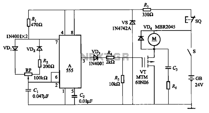
The adjustment potentiometer (RP) allows for modification of the duty cycle of a square wave generated by the 555 integrated circuit (IC) in New Zealand, enabling control of motor speed within a range of 0 to 100%. The circuit utilizes...
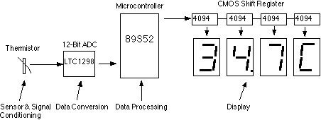
This assignment pertains to the course "Designing Microprocessor Based Instrumentation." The project features a board that utilizes a 12-bit ADC, a C program with digital filtering, and an LED display interface. It achieves a temperature reading sensitivity of 0.1°C....