
1-Wire Barometer Calibration
The circuit described utilizes the MPX4115 barometric pressure sensor, which is a piezoresistive transducer that generates a voltage output proportional to the applied pressure. The sensor operates effectively within the specified pressure range, providing a resolution that is suitable for various applications, including weather monitoring and altitude measurement.
The integration with the DS2438 Smart Battery Monitor allows for a seamless interface with the 1-Wire network, enabling data logging and monitoring of the pressure readings. The op-amp stage is critical for amplifying the sensor's output, ensuring that the signal levels are compatible with the A/D converter. The use of potentiometers for gain and offset adjustments provides flexibility in calibration, allowing for fine-tuning based on specific environmental conditions and sensor characteristics.
The RC filter preceding the op-amp stage serves to smooth out any noise in the signal, enhancing the accuracy of the readings. The design's modularity, with the ability to change resistor values and input sources, allows for customization based on the specific requirements of the application. The mention of calibration procedures highlights the importance of ensuring measurement accuracy, particularly in dynamic environments where pressure changes frequently occur.
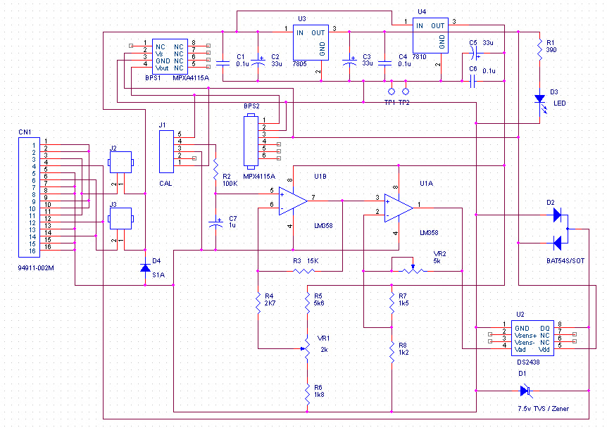
Overall, this circuit design presents a robust solution for accurately measuring barometric pressure, with detailed attention to calibration and adaptability for different operational scenarios. The comprehensive approach to design and calibration ensures that users can achieve reliable and precise barometric measurements over time.The resolution of the barometric pressure is about 0. 00417 inHg (0. 0139 kPa) for a pressure range of 31. 0 to 28. 0 inHg (105. 0 to 95. 0 kPa, or 1050 to 950 mb or hPa). Better resolutions are possible with a more restricted pressure range. The circuit requires an additional power source other than that of the 1-Wire network. The MPX4115 requires abou t 7 ma of current. This is more than a 1-Wire network can provide without an elaborate circuit to store parasitic power from the 1-Wire network for short burst of current for pressure measurements. For barometric pressures the MPX4115 output voltage ranges from about 4. 25 to 3. 79 volts at sea level, and about 2. 77 to 2. 45 volts at 10, 000 feet. Most of this range is above the active voltage range of a 5 volt opamp circuit. In effect the sensor voltage is referenced to the power supply, not ground as desired. Fortunately the DS2438 Smart Battery Monitor accepts inputs as high as 10 volts. Thus by powering an opamp from 10 volts the output of the MPX4115 is well in the opamp and DS2438 range.
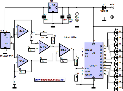
The MPX4115 output is fed through a RC filter to opamp stage, U1B, which has a fixed gain of approximately 4. This stage has an adjustable voltage input which is added to the barometric sensor output within the opamp, thereby allowing the adjustment of the output voltage offset to the A/D converter.
The two 10-turn potentiometers (pots) control the gain and offset. VR2 controls the gain of U1A and VR1 controls the offset of the output voltage to the 1-Wire DS2438 A/D converter. Note that the MPX4115 feeds R2 through a jumper on J1. This allows easy change of the input voltage from a source other than the MPX4115 like the calibration tool.
The design presented in the schematic above is not the only possible barometer configuration the values of the resistors can be modified for different ranges of barometric pressure and resolutions. Dave Bray has provided Excel Spreadsheets for modifying the design for different barometric pressure ranges and resolutions, and for pre-calibration of the two pots.
Version 3. 0. Large schematic with full details, parts list, version 3. 0 simulator, and calibration details. Needed to help construction, for option modifications, and calibration. Once you have constructed your barometer and done the initial calibration, it is recommended that you do a final calibration after the barometer has been operated for several days. Getting your barometer accuracy calibrated will take adjustment over several cycles of barometric pressure change.
The initial calibration will not be accurate unless your MPX4115 has the same output vs pressure slope as the typical sensor. Our recommendation is that you do not attempt to adjust the potentiometers of your barometer until you create a spreadsheet of local airport pressure vs your readings, and do this for a significant number of readings over a range of pressures.
Following is a 14 day data spreadsheet with a pressure range of 1. 27 inHg - 29. 31 to 30. 58. The barometer was calibrated for a range of 28. 8 to 30. 8, giving a resolution of 0. 01 inHg. (This data was obtained from the David Bray Barometer V1. 1a. ) Once you have those results you can use a linear trendline (regression) to find the slope of local vs airport readings. If the trendline slope is not 1. 0, use that slope to correct your gain resistor VR2. The slope will be a multiplicitive change to the current VR2 resistance. For example: if current VR2 resistance is 3K and the slope is 1. 05, change VR2 to 3K/1. 05 = 2. 85K. Before you spend too much time getting an accurate calibration you should decide what range of pressure changes you want to track and what range of output voltages of U1A you consider satisfactory.
3. Collect data for a spreadsheet by changing J1 pin 4 input in small steps recording the voltages at J1 pin 4 and LM358 pin 7. Plot it on the spread sheet. Following is a sample graph 🔗 External reference
Related Circuits
Construction of a 1-Wire Barometer. This page shows the circuit and provides construction and calibration details. This barometer connects to a Dallas Semiconductor 1-Wire network. The 1-Wire Barometer is designed to measure atmospheric pressure and transmit this data over a...
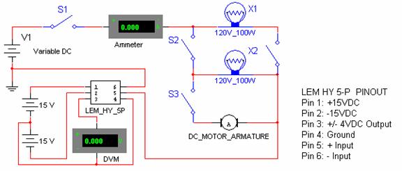
Connect the negative side of the positive supply to the positive side of the negative supply to create a ±15 VDC. This junction serves as the ground for the transducer, ensuring a balanced voltage. Continue the experiment by switching...
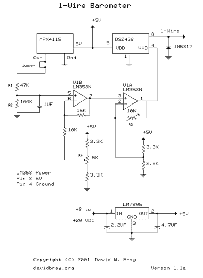
This design uses a Motorola MPX4115 Silicon Pressure Sensor, a Dallas Semiconductor DS2438 Smart Battery Monitor (to perform 1-Wire analog to digital conversion), an operational amplifier, a voltage regulator, a diode, and several resistors and capacitors. The circuit requires...

The 1-Wire Net, or MicroLAN (by Maxim-Dallas), is a straightforward method for connecting slow devices such as sensors, relay drivers, and switches using basic components. These components include a 1-Wire protocol handler, an interface to the external world, and...
While it may lack the aesthetic appeal of traditional mercury barometers featuring elongated glass tubes mounted on intricately carved wood, the Torricelli barometer presented here serves as a functional equivalent and an electronic representation of the original Torricelli barometer....
Temperature indicators and temperature-based products have garnered significant interest due to their numerous applications and various possible solutions, each presenting unique advantages and disadvantages. This concept focuses on a sensor interface that delivers high accuracy while minimizing board space....