
Electronic Torricelli Barometer

The electronic Torricelli barometer circuit is designed to accurately measure atmospheric pressure and display it using an LED scale. The heart of the system is the Motorola MPX2200AP pressure sensor, which converts the physical pressure into a corresponding voltage output. This sensor operates on the principle of differential pressure measurement, making it suitable for atmospheric conditions.
To ensure accurate readings, the circuit includes a voltage regulation component (IC1), which stabilizes the supply voltage, thus preventing fluctuations that could affect the sensor's output. The low-level differential output from the MPX2200 is amplified using four operational amplifiers within an LM324 IC. These amplifiers are configured to provide sufficient gain to ensure that the output voltage is compatible with the input requirements of the LM3914 LED driver.
The LM3914 is a versatile LED bar graph driver that can control a series of LEDs to visually represent the input voltage. By leveraging resistors R7 and R8, the circuit expands the measurement range, allowing for a more granular display of atmospheric pressure changes. The use of a potentiometer (P1) for calibration enables the user to align the LED display with the actual atmospheric pressure, ensuring that the readings are both accurate and reliable.
The design also accounts for environmental considerations by replacing the toxic mercury with a safer LED display, contributing to a more sustainable approach to pressure measurement. The overall circuit design is compact and efficient, making it suitable for both hobbyist and professional applications in meteorology and environmental monitoring.Although it does not have the same charm as real mercury barometers with long glass tubes on pieces of carved and polished wood, the Torricelli barometer discussed here is a functional equivalent and electronic replica of the Torricelli barometer. Actually, rather than displaying the atmospheric pressure on the traditional digital displays, we pre
ferred to reproduce the general look of this respected predecessor of electronic barometers. The mercury tube is, of course, replaced by a simple LED scale which, if not as beautiful, is still less toxic for the environment in case of breakage. As indicated on the drawing, the pressure sensor utilized is a Motorola MPX2200AP. This circuit is adapted for measuring absolute pressure and has a range well suited for atmospheric pressure.
Without entering too deep into the technical details, such sensors deliver an output of voltage proportional not only to the measured pressure but, unfortunately, to their supply voltage as well. Hence they must be powered from a stable voltage which is ensured here by the use of IC1. Since the output of the MPX2200 is differential and at a very low level, we had to resort to the use of four operational amplifiers IC4.
A to IC4. D, contained in one LM324, to obtain levels that can be processed easily. As long as potentiometer P1 is adjusted correctly, this group of operational amplifiers delivers a voltage of 1 volt per atmospheric pressure of 1, 000 hPa to the LM3914. Since the atmospheric pressure will be within the range 950 to 1040 hPa at sea level, we need to make an expanded-scale voltmeter with this LM3914 in order to better exploit the 10 LEDs that it can control.
That is the role of resistors R7 and R8 which artificially raise the minimum voltage value the chip is capable of measuring. Consequently, we can calibrate` our LED scale with one LED per 10 hPa and thus benefit from a measurement range which extends from 950 hPa to 1040 hPa.
In principle, you should not have a need to go beyond that in either direction. The circuit may be conveniently powered from a 9-volt battery but only if used very occasionally. Since this is usually not the case for a barometer, we advise you to use a mains adaptor instead supplying approximately 9 volts. Calibration basically entails adjusting the potentiometer P1 to light the LED corresponding to the atmospheric pressure of your location at the time.
Compare with an existing barometer or, even better, telephone the closest weather station. They will be happy to give you the information. After Evangelista Torricelli, 1608-1647, Italian physician who proved the existence of atmospheric pressure and invented the mercury barometer. 🔗 External reference
Related Circuits
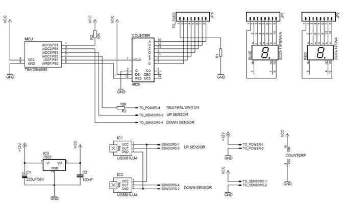
This is a new design for a universal gear indicator that can be fitted to any motorcycle as an aftermarket accessory. Its main advantage is that its operation depends entirely on the gear shift lever movement, instead of connecting...
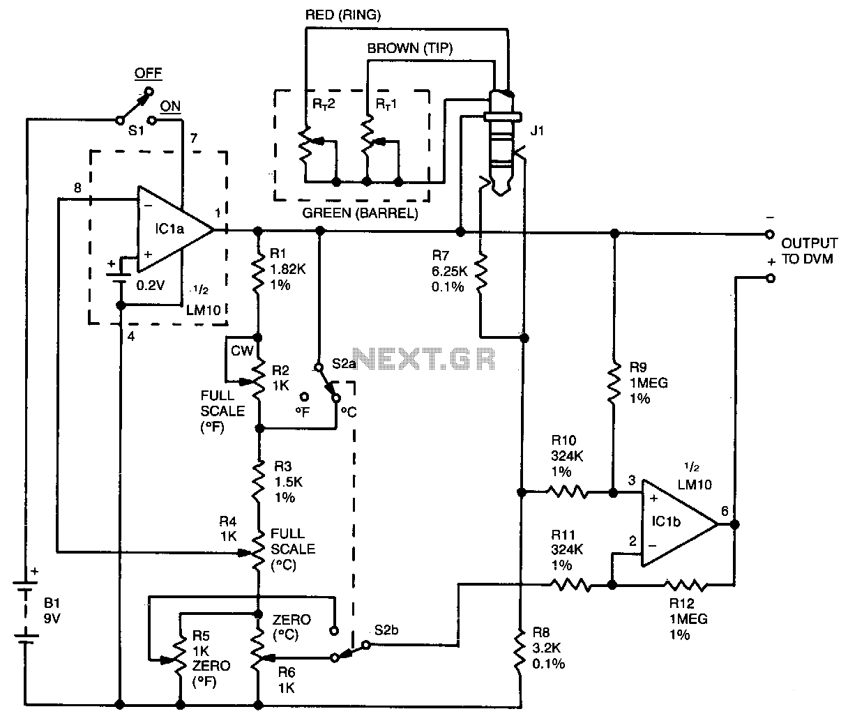
This oscillator circuit features a quartz crystal with a nominal resonant frequency of 262,144 Hz, which is cut in an orientation that provides a significant linear coefficient of frequency variation with temperature. In this configuration, the oscillation frequency is...
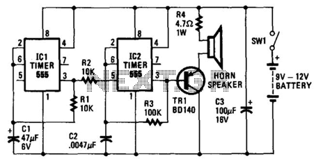
The oscillator based on IC2 generates sound, with its output connected to the base of TR1, which amplifies the signal to drive the speaker. Resistor R4 limits the current through TR1 to a safe level. The oscillation frequency of...
This review highlights a dual-test scenario involving the FVP preamp, with initial contacts made with Vacuum State and insights provided by Geoff during a trip to Brittany. The FVP was sent to France for evaluation. Geoff tested the FVP5A...
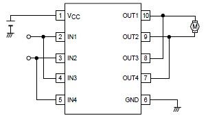
A simple forward-reverse motor control driver electronic circuit can be designed using the LB1948M, a two-channel low saturation voltage forward-reverse motor control driver IC. The LB1948M motor driver is suitable for use in 12V system products and can drive...
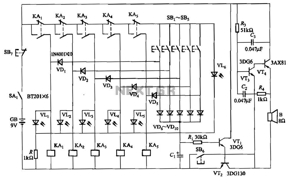
A relay-style circuit designed for a five electronic responder group. This circuit features self-locking capabilities, sound and light displays, time monitoring, and additional functions. The circuit includes a monitoring time button operated by the moderator. When this button is...