
Current Sensor Testing and calibration
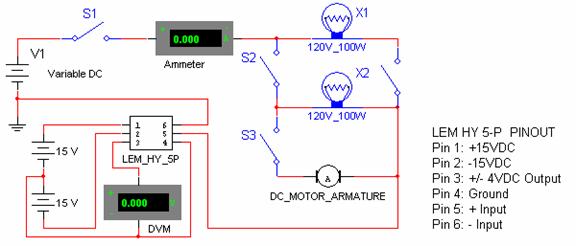
To implement the described circuit, a dual power supply configuration is necessary to achieve the ±15 VDC output. This can be accomplished by utilizing two separate voltage sources: one providing +15 V and the other -15 V. The negative terminal of the positive supply (+15 V) should be connected to the positive terminal of the negative supply (-15 V). This connection creates a common ground point, which is essential for the proper operation of the transducer and ensures that the voltage levels remain balanced during measurements.
The transducer operates within this voltage range, allowing for accurate readings of the output voltage in relation to the input current. The relationship defined by the equation Output (Volts) = 0.8 * Input (Amps) indicates a linear correlation between the input current and the output voltage, which is critical for applications requiring precise voltage control based on current variations.
During experimentation, it is important to switch off the power supply before changing the load to prevent any potential damage to the components or inaccurate readings. After adjusting the load, the circuit can be energized again to measure the new current values and corresponding transducer outputs.
For current measurement, a digital ammeter is utilized for lower current ranges (0 to 2.0 Amps) due to its accuracy and ease of use. For higher currents, where the digital ammeter may be limited, an analog ammeter is employed, particularly one calibrated to a 5 Amp scale. This ensures that all current readings, regardless of the range, are accurately captured and can be used to validate the relationship established by the experimental data against the manufacturer’s specifications.
Overall, the described circuit and measurement methodology provide a structured approach to analyzing the performance of the transducer under various load conditions, confirming the accuracy of the data sheet values through empirical testing.Connect the Negative side of the positive supply to the Positive side of the negative supply to create a +/-15vdc. This junction is the ground for the transducer to ensure a balanced voltage. 9) Continue the experiment by switching the power off, changing the load, and energizing the circuit to read different currents and different transducer o
utputs. The data recorded from the experiment shows that Output(Volts)=0. 8*Input(Amps). Since we know from the data sheet that 4 volts = 5 Amps, or 0. 8 v = 1 A, the data confirms the data sheet value. All data points recorded between 0 and 2. 0 Amps was measured using a digital ammeter. Due to the limitations of the digital ammeter, readings above 2. 0 Amps was measured using an analog ammeter on a 5 Amp scale. 🔗 External reference
Related Circuits
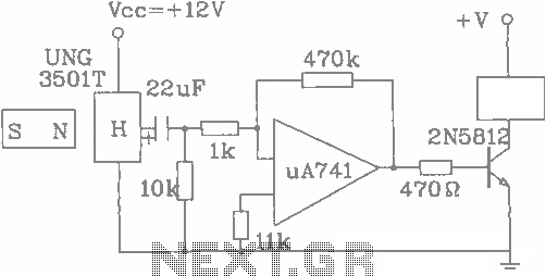
The UGN-3501T Hall sensor features a highly sensitive counter circuit diagram, allowing it to detect very small changes in magnetic fields. This capability enables the detection of ferrous metals. Utilizing this characteristic, it can be employed to count loads....
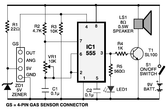
This schematic diagram represents an LPG gas leakage sensor alarm circuit powered by a 9V PP3 battery. A Zener diode (ZD1) is utilized to convert the 9V input into 5V DC, which is required to operate the gas sensor...
Scopeclock is a user-friendly hardware device designed to enhance the functionality of X-Y capable analog oscilloscopes. This hardware allows for the conversion of an analog oscilloscope into a scope clock. The project was developed by a team at CEDT...
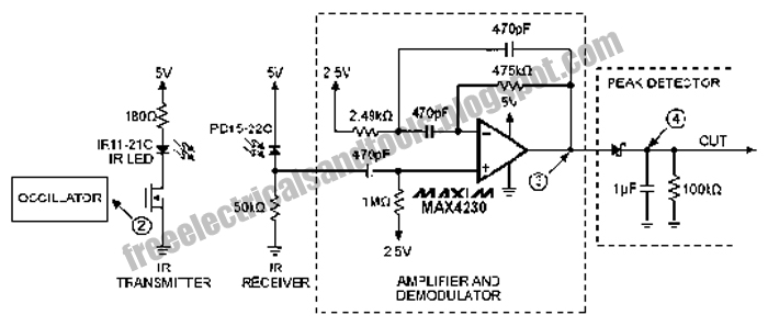
The following circuit illustrates an Infrared Proximity Sensor Circuit Diagram. This circuit is based on the MAX4230 integrated circuit. Features include a 10 kHz oscillator. The Infrared Proximity Sensor Circuit utilizing the MAX4230 integrated circuit is designed to detect the...
Using LM134 and LM10 integrated circuits, a thermometer can be constructed with a sensing range of -55 to 150 °C. The ideal meter for this circuit is a 0-200 µA. The proposed thermometer circuit utilizes the LM134, a current source...

An ultra-simple circuit of the tilt sensor alarm can be fabricated using readily available, inexpensive components. The circuit operates as a true transistor-based design. The tilt sensor alarm circuit utilizes a tilt sensor, which is a device that detects the...