
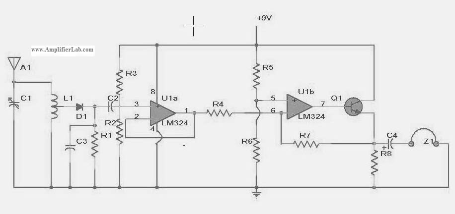
10.7 MHz RF Amplifier And Filter
The 10.7 MHz RF amplifier and filter circuit is designed to amplify radio frequency signals while simultaneously filtering out unwanted frequencies. This circuit typically employs a power MOSFET, which is favored for its high efficiency and ability to handle high-frequency signals. The circuit can be divided into two main sections: the amplifier stage and the filter stage.
In the amplifier stage, the MOSFET operates in the active region, where it amplifies the input RF signal. The gate of the MOSFET is connected to the input signal through a coupling capacitor, which blocks any DC component while allowing the AC RF signal to pass. The drain of the MOSFET is connected to a load resistor, which converts the amplified RF signal into a usable output. Biasing resistors are also included to ensure the MOSFET operates within its optimal range.
The filter stage follows the amplifier and is designed to select the desired frequency of 10.7 MHz while attenuating other frequencies. This is typically achieved using a combination of inductors and capacitors configured in a low-pass or band-pass filter topology. The choice of components and their values is critical for defining the filter's cutoff frequency and bandwidth.
To ensure stability and minimize distortion, feedback mechanisms may be included in the design. This can be done by incorporating a feedback resistor that connects the output back to the input, providing a portion of the output signal to the input, which helps stabilize the gain of the amplifier.
Overall, this circuit is essential in applications such as radio receivers and communication systems, where precise amplification and filtering of RF signals are required for effective signal processing. Proper layout and component selection are crucial to minimize parasitic capacitances and inductances that could affect the performance of the circuit at high frequencies.he following circuit shows about 10.7 MHz RF Amplifier And Filter Circuit Diagram. Features: capacitances of a power MOS-FET become significant, .. 🔗 External reference
Related Circuits
The EDFET drives like a FET, but with the bias stability of bipolar. Amps of output current can be controlled by milliamps of input current. The current gain is a design choice dictated by bandwidth. Two of things you...
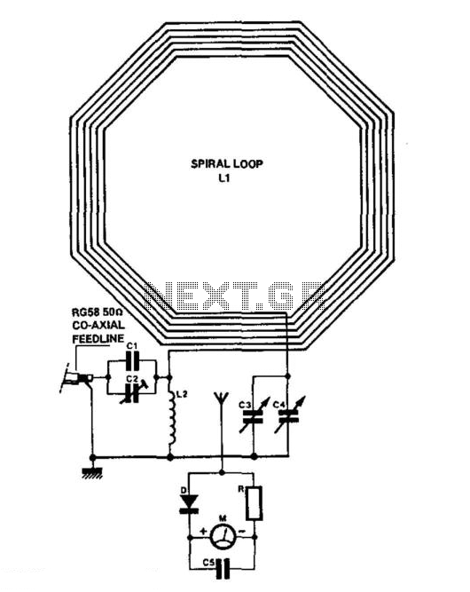
C1 = 3750 pF 500 V silver-mica capacitor. C2 = 100 pF preset capacitor (Jackson C803). C3 = 75 pF variable capacitor (Jackson C809) with a knob. C4 = 12.7 pF variable capacitor (Jackson C16) with a knob. C5...
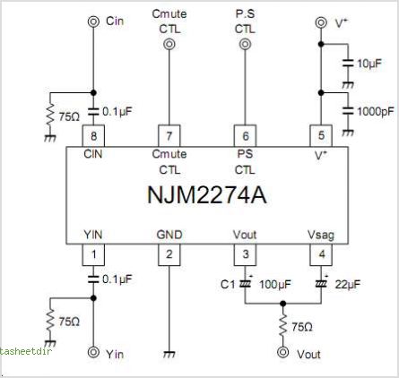
The NJM2574 is a low voltage video amplifier that includes a low-pass filter (LPF) circuit, a driver, and an internal clamp/bias function. It is designed to connect directly to a TV monitor using a composite input signal of 0.5V...
The following circuit illustrates a power amplifier electronic circuit, specifically a tube audio RF amplifier circuit diagram. This circuit is based on the LM324 integrated circuit. The power amplifier circuit utilizing the LM324 operational amplifier is designed to enhance audio...
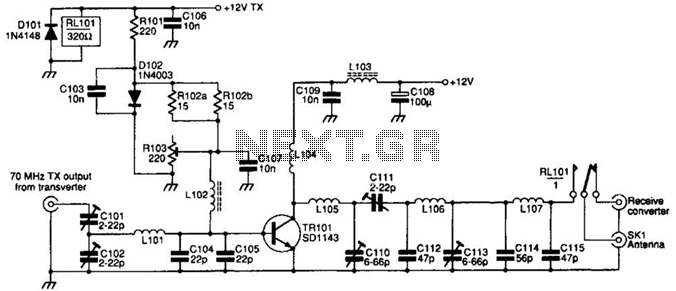
The SD1143 transistor offers a gain of approximately 14 dB in this circuit. Its design takes advantage of the fact that a 175-MHz device exhibits significantly higher gain when operated at lower frequencies. The amplifier was initially intended for...

This is a stereo audio amplifier designed for automotive applications. The circuit utilizes a single integrated circuit, the TDA1553, along with several external components. This IC is responsible for managing the stereo audio system in a vehicle. The TDA1553CQ...
Warning: include(partials/cookie-banner.php): Failed to open stream: Permission denied in /var/www/html/nextgr/view-circuit.php on line 713
Warning: include(): Failed opening 'partials/cookie-banner.php' for inclusion (include_path='.:/usr/share/php') in /var/www/html/nextgr/view-circuit.php on line 713