
70Mhz Rf Power Amplifier Circuit
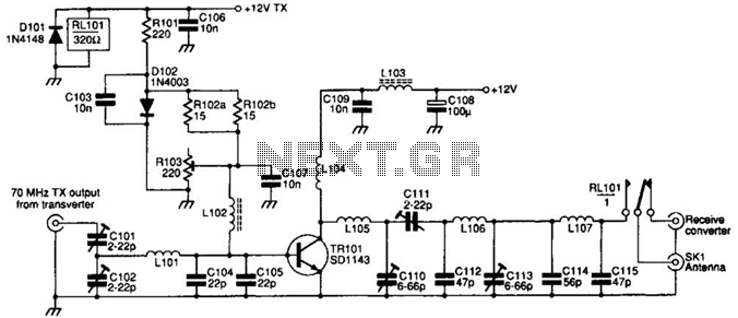
The SD1143 transistor is a high-frequency device that excels in low-frequency applications, making it suitable for various amplification tasks. In this circuit configuration, the transistor operates within its optimal gain range, leveraging its characteristics to enhance signal strength effectively. The 14 dB gain indicates that the output signal is 14 times more powerful than the input, which is critical for applications needing robust signal amplification.
The circuit is designed to take a modest input power of 300 to 500 mW and amplify it to a substantial output power of 8 to 10 W. This level of amplification is particularly beneficial in transverter applications, where the signal must be boosted before transmission or further processing. The efficiency of the SD1143 in this role allows for effective communication over extended distances, making it an essential component in RF (radio frequency) systems.
The design considerations for this circuit include the careful selection of passive components, such as resistors and capacitors, to ensure stability and minimize distortion. Proper biasing of the transistor is also crucial to maintain linear operation and prevent thermal runaway. Additionally, attention must be paid to the layout of the circuit to reduce parasitic inductance and capacitance, which can adversely affect performance at higher frequencies.
Thermal management is another important aspect of the circuit design, as the transistor will generate heat during operation. Adequate heat sinking and ventilation must be implemented to ensure reliable operation and longevity of the SD1143 transistor within the circuit. Overall, this amplifier circuit represents a well-engineered solution for achieving significant power amplification in RF applications. The SD1143 transistor provides a gain of about 14 dB in this circuit. It uses the fact that a 175-MHz device has a much higher gain when used at lower frequencies. The amplifier was originally designed to be used with a transverter. The output is 8 to 10 W for a 300- to 500-mW input. 🔗 External reference
Related Circuits
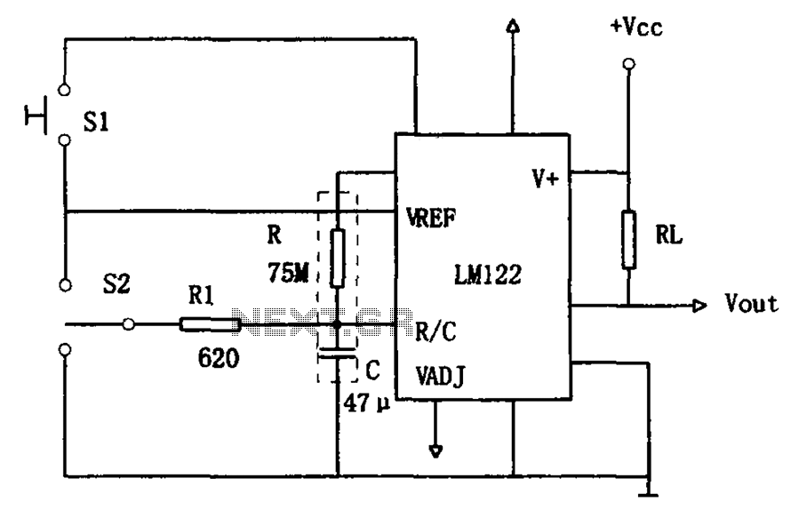
The circuit utilizes an LM122 timer, as illustrated in Figure 1, to manage various timing operations, including starting, resetting, and halting the process midway through. The operation of the circuit is governed by switching mechanisms. Switch S1 initiates the...
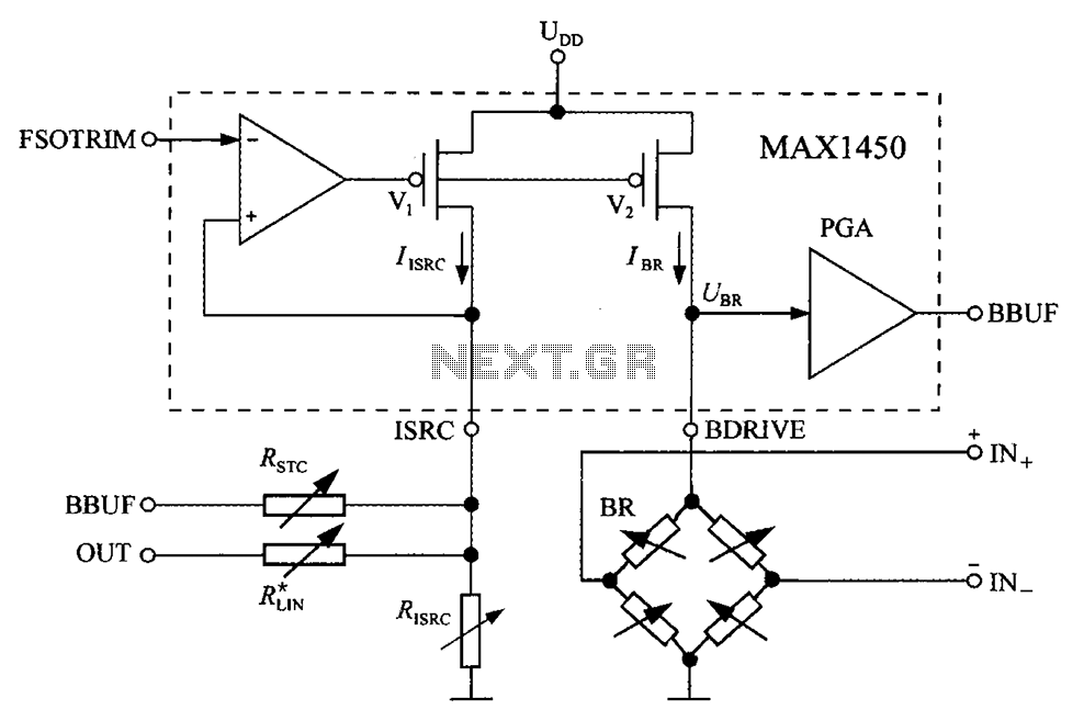
The circuit diagram for the bridge integrated pressure signal conditioner MAX1450 is composed of various components. The MAX1450 is a high-performance integrated circuit designed for signal conditioning in pressure sensing applications. It is particularly suited for use with resistive bridge...
The PT2399 digital echo circuit schematic is an electronic design that utilizes the PT2399 integrated circuit (IC) for audio applications. This digital echo processor, based on CMOS technology, incorporates both analog-to-digital conversion (ADC) and digital-to-analog conversion (DAC) processes for...
This circuit is very basic to build and puts out great power for your car or home. Keep all leads as short as possible. The described circuit is a fundamental power amplifier, suitable for applications in automotive or residential settings....
Nissan Sentra 1.6 Liter Manual Transmission Starter Circuit Wiring Diagram. The Nissan Sentra 1.6 Liter manual transmission starter circuit wiring diagram provides a visual representation of the electrical connections involved in the starting system of the vehicle. This diagram is...
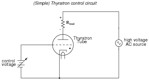
An often neglected area of study in modern electronics is that of tubes, more precisely known as vacuum tubes or electron tubes. Almost completely overshadowed by semiconductor, or "solid-state" components in most modern applications, tube technology once dominated electronic...