
10 Dancing LEDs

The circuit operates by utilizing audio signals captured from the environment via a microphone, which serves as the primary input. The microphone's output is first amplified by operational amplifier IC1A, providing a gain of approximately 100. This amplified signal is then fed into IC1B, which functions as a peak-voltage detector. The output from IC1B generates a pulse corresponding to the peaks of the audio signal, which is critical for synchronizing the LED illumination with the rhythm of the music or speech.
The output pulses from IC1B are utilized to clock IC2, a ring decade counter. This counter is capable of sequentially driving up to ten outputs, each connected to an LED. The result is a visually dynamic display where the LEDs illuminate in a sequence that corresponds to the rhythm detected in the audio signal.
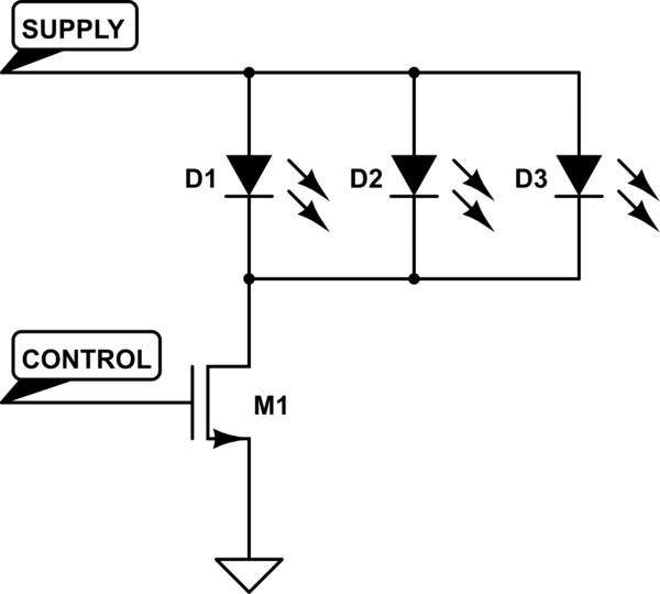
For the expanded version of the circuit, the design accommodates the driving of LED strips. Each strip can consist of up to five LEDs, and the entire setup operates at a 9V power supply. The constant current source, constructed from transistors Q1 and Q2, ensures that each LED strip receives a stable 10mA current, which is crucial for consistent brightness across the LED strips.
Transistor Q3 acts as a switch, allowing the control of individual LED strips. Each strip requires its own transistor and associated base resistor to ensure proper operation. The configuration of series-connected LEDs within each strip allows for flexibility in design, as the number of LEDs can be adjusted based on the desired brightness and voltage drop across the LEDs.
Overall, this circuit exemplifies a practical application of audio signal processing in a visual display context, effectively combining sound detection with LED control to create an engaging user experience.The basic circuit illuminates up to ten LEDs in sequence, following the rhythm of music or speech picked-up by a small microphone. The expanded version can drive up to ten strips, formed by up to five LEDs each, at 9V supply. IC1A amplifies about 100 times the audio signal picked-up by the microphone and drives IC1B acting as peak-voltage detector.
Its output peaks are synchronous with the peaks of the input signal and clock IC2, a ring decade counter capable of driving up to ten LEDs in sequence. An additional circuit allows the driving of up to ten strips, made up by five LEDs each (max.), at 9V supply.
It is formed by a 10mA constant current source (Q1 & Q2) common to all LED strips and by a switching transistor (Q3), driving a strip obtained from 2 to 5 series-connected LEDs. Therefore one transistor and its Base resistor are required to drive each of the strips used. 🔗 External reference
Related Circuits
A Common Cathode LED strip is being utilized instead of a Common Anode variant, leading to the development of a modified circuit. The experience with FETs was limited, resulting in challenges as a minimum voltage equal to Vcc is...
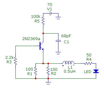
This article presents basic circuits for pulsing infrared LEDs and low-power visible semiconductor lasers utilizing inexpensive and readily available components. Numerous interesting and practical applications are referenced, alongside several online resources. The focus of the article is on the...

This slideshow is based on the LED Design Ideas Collection, which features a compilation of LED-related circuits and design applications submitted by readers and published in EDN's Design Ideas section. Users can browse through the circuit schematics in this...
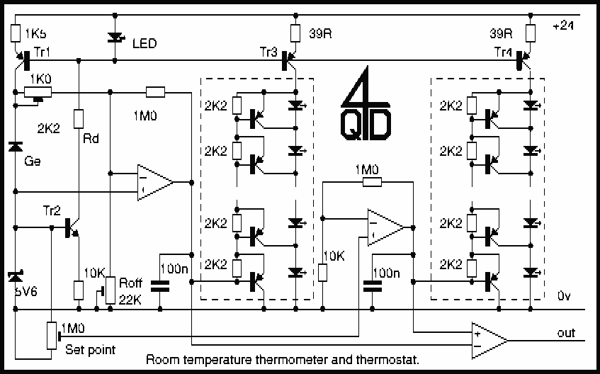
This circuit uses a germanium diode (marked Ge) as a temperature sensor. I used an OA90 diode but others should do. The 'ring' of Tr1 and Tr2 bias each other. Tr1's collector current is stabilized by the 5v6 zener,...
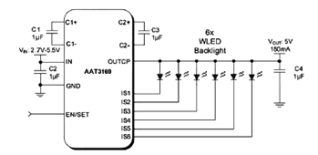
The parallel arrangement of LED backlights allows the control IC to utilize inexpensive low voltage CMOS processes, as illustrated in the following circuit diagram, which requires two to six white LEDs (WLEDs) in parallel. In many applications, LED backlights...
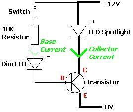
A transistor is an electronic component that allows a small current to control a significantly larger current. This characteristic is valuable in various renewable energy projects and other applications. A basic circuit diagram is provided, featuring a 12V LED...