
led strip Using a N-Mosfet to switch a common cathode ledstrip

In this circuit, a Common Cathode LED strip is employed, and the control of brightness is achieved using a Pulse Width Modulation (PWM) signal at 5V. The STP50N06FI N-channel MOSFET is selected for its capability to handle the current requirements of the LED strip.
To implement this circuit effectively, the MOSFET gate must be driven by a PWM signal from a microcontroller or similar device. The source of the MOSFET is connected to the ground, while the drain is connected to the negative terminal of the LED strip. The positive terminal of the LED strip is connected to the power supply (Vcc).
For proper operation, the PWM signal should be configured to switch between 0V and 5V, allowing the MOSFET to turn on and off rapidly. When the gate receives a high signal (5V), the MOSFET enters saturation, allowing current to flow through the LED strip, thereby illuminating it. Conversely, when the gate signal is low (0V), the MOSFET turns off, cutting off the current and turning off the LEDs.
To ensure the MOSFET operates correctly, it is essential to include a pull-down resistor on the gate to prevent floating states when the PWM signal is not active. A typical value for this resistor can range from 10kΩ to 100kΩ. Additionally, a flyback diode may be implemented across the LED strip to protect the MOSFET from voltage spikes generated by the inductive load when the LEDs are turned off.
This configuration allows for effective dimming of the LED strip by varying the duty cycle of the PWM signal, thus controlling the average power delivered to the LEDs and achieving the desired brightness levels. It is crucial to verify that the MOSFET's specifications, including the maximum current and voltage ratings, are suitable for the application to prevent component failure.As I am using a Common Cathode led-strip instead of a Common Anode one as used in the above link thus I came up with this `modified circuit`. Because my experience with FETs was nihil this didn`t actually work as I would need at least a voltage => Vcc to saturate the MOSFET.
VCC + STP50N06FI | N-MOSFET | |-+ _ |<- | \_-|-+ |_/ | Logic 5V (PWM) | Ledstrip V -> (Common - Cathode) | | = GND (created by AACircuit v1. 28. 6 beta 04/19/05 Is it possible to use a N-channel MOSFET at all for this application and if so, what do I need to do to make this work (Control the LED-strip brightness with a PWM signal, logic 5v). 🔗 External reference
Related Circuits

This simple circuit will energize and de-energize a relay at the push of a button. Any type of momentary action push-to-make switch can be used. Pushing the button once will energize the relay. And pushing it a second time...

In the example above, a low voltage (12V DC) is utilized to activate a relay that switches a 240V AC main circuit. It is important to note that there is no electrical connection between the two circuits within the...

In this application, a BA1404 is utilized to generate an FM MPX baseband signal. This signal modulates a crystal oscillator (Q3) through a dual varactor series modulator. This transmitter can be used to play CD audio on an existing...

A circuit is being designed that incorporates two key switches, which must both be closed for current to flow through the circuit. The proposed circuit configuration employs two key switches connected in series. In this arrangement, the current can only...
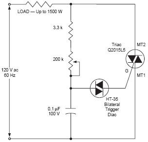
The DIAC, or diode for alternating current, is a trigger diode that conducts current only after its breakdown voltage has been momentarily exceeded. Most DIACs are utilized in applications requiring a switching function in AC circuits. The DIAC is a...

A bicycle typically does not have a turning light. When a cyclist wants to turn, it can be dangerous as vehicles following may not be aware of the turn. To enhance safety, a turning light circuit for bicycles can...