
Room thermometer with LEDs
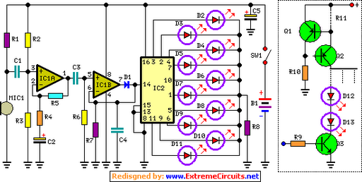
This circuit employs a germanium diode as a temperature sensor, leveraging its unique characteristics to measure temperature changes effectively. The OA90 diode is a suitable example, though other germanium diodes can be utilized. The circuit comprises two transistors, Tr1 and Tr2, which are configured in a feedback arrangement to stabilize the collector current of Tr1. A 5.6V zener diode is integrated into the design to maintain a constant voltage, allowing Tr2 to operate at approximately 5mA. This current flows through an LED, generating a bias voltage of about 1.5V for Tr1, thereby stabilizing the current through the germanium diode.
The voltage across the germanium diode is influenced by its leakage current, necessitating potential adjustments to the 1.5kΩ resistor to achieve an optimal range, particularly when using different diode types. The output voltage from the diode is inverted by a section of an LM339 comparator, which is repurposed as an operational amplifier (op-amp). This inverted voltage drives an LED line, which serves as a visual thermometer.
The circuit is designed to function as a room temperature thermometer and thermostat, controlling central heating systems. It features two lines of LEDs: one indicating the actual temperature and another representing the set point. The design allows for calibration of the temperature range and slope, with adjustments made via resistors Rd and Roff. These resistors enable fine-tuning of the sensitivity, allowing for a response of 0.5 degrees per LED, if desired.
The second LED line, also driven by an op-amp, mirrors the first and indicates the set point. A preset adjustment for the set point alters the illumination of this second LED line. The circuit includes a third comparator that monitors the voltage levels of the two LED lines, changing state when the actual temperature surpasses the set point, providing an output signal when the desired temperature is reached.
The entire circuit operates on a 24V power supply, with consideration given to the voltage requirements of the LEDs. A standard red LED typically requires around 1.6 volts, thus necessitating approximately 16 volts for ten LEDs in the design. The reverse leakage current of the germanium diode is a significant factor, as it varies linearly with temperature, making it a more suitable choice compared to silicon diodes, which exhibit minimal leakage. This characteristic enhances the circuit's performance in temperature sensing applications. This circuit uses a germanium diode (marked Ge) as a temperature sensor. I used an OA90 diode but others should do. The 'ring' of Tr1 and Tr2 bias each other. Tr1's collector current is stabilized by the 5v6 zener, causing Tr2 to operate at about 5mA: this collector current flows through the LED to generate about 1.5v bias for Tr1 so the current through the Ge diode is stabilized. The voltage across the diode will depend on its leakage current and you may need to alter the 1K5 to get a sensible range with a different diode.
The voltage across the diode is inverted by the first 'op-amp' (in fact one section of an LM339 comparator used as an op-amp) to drive the LED line, shown in the pecked box. This LED line has been explained elsewhere on 4QD's pages, but it is biased at constant current by Tr3.
This is a fun circuit which is also something useful: I had this working for several years as a room temperature thermometer and thermostat to control the central heating. It has a germanium diode to sense the temperature, a line of LEDs acting as a thermometer and a second line of LEDs to show the 'set point'.
When the actual temperature display passes the 'set point' display, the thermostat switches. There is one slight problem with GE diodes: although the leakage any diode has a very linear slope with temperature, it is very difficult to find two diodes with the same slope. That means you need to calibrate for range and slope. Rd adjusts the slope, i.e. the number of degrees per LED and Roff adjusts the offset, i.e. the centre of the range. The thermometer can be set to be quite sensitive, 0.5 degrees per LED if you wish. The second LED line and op-amp duplicates the first. I used this to show the set-point. Adjusting the 'Setpoint' preset makes the illumination of the second line rise and fall. The third comparator senses the two LED line drive voltages and changes state when they cross. So you get an indication of the actual temperature, and the set temperature and an output when the set is reached.
The whole circuit worked from a 24v supply: remember that a standard red LED needs about 1.6 volts so the ten LEDs that I used (I've shown the top and bottom pair) need about 16 volts. The reverse leakage current in a diode is a very strong and linear function of temperature. Unfortunately the leakage in a normal silicon diode is so small you can forget it. However a germanium diode is another matter entirely. 🔗 External reference
Related Circuits
The goal is to utilize a PC to measure the outdoor temperature using a serial-connected device equipped with a probe that can be conveniently placed outside. Although various options were found through online searches, many appear to be overly...

Acoustic thermometry is utilized in environments with extreme operating temperatures, such as cryogenics and nuclear reactors. The transducer consists of Polaroid ultrasonic material, which is mounted at one end of a sealed 6-inch long Invar tube. The medium within...
The basic circuit illuminates up to ten LEDs in sequence, synchronized with the rhythm of music or speech detected by a small microphone. The expanded version can drive up to ten strips, each consisting of up to five LEDs,...
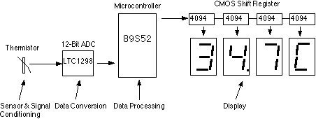
This assignment pertains to the course "Designing Microprocessor Based Instrumentation." The project features a board that utilizes a 12-bit ADC, a C program with digital filtering, and an LED display interface. It achieves a temperature reading sensitivity of 0.1°C....

The ICL7106 integrated circuit contains all the active circuitry for a 3 1/2 digit panel meter (DPM) in a single chip. It was designed to interface directly with a liquid crystal display (LCD). The potential difference across a silicon...

This is a tutorial for beginners who have recently started learning about electronics. The author has prior experience in programming with C and Python. The schematic presented in this tutorial is designed for novice electronics enthusiasts who are transitioning from...
Warning: include(partials/cookie-banner.php): Failed to open stream: Permission denied in /var/www/html/nextgr/view-circuit.php on line 713
Warning: include(): Failed opening 'partials/cookie-banner.php' for inclusion (include_path='.:/usr/share/php') in /var/www/html/nextgr/view-circuit.php on line 713