
Example Transistor Circuit with LEDs
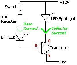
The rationale for employing a transistor in this circuit becomes evident when considering scenarios with multiple low-powered bulbs. For instance, if 100 spotlight bulbs were to be switched on and off with a single switch, the total current required would reach five Amps. A switch capable of directly handling this current would need to be rated above five Amps, which is typically more expensive and larger compared to lower-rated switches. By integrating a power transistor rated for over five Amps, the overall design remains compact, cost-effective, and potentially more reliable over time. Low current switches are inexpensive; for example, a PCB-mounted slide switch rated for up to 30 volts DC and 0.2 Amps costs around 11p and measures merely 8.5 x 3.5mm. Thus, transistors are essential for minimizing the size and cost of electronic circuits, enabling efficient control of higher power loads with minimal input current.A Transistor is an electronic component which enables a small current to control a much larger current. This feature is very useful in many renewable energy projects and other applications. Click here to read our Introduction to Transistors. Pictured below is a very basic circuit incorporating a transistor. A 12V LED Spotlight bulb (labelled LED Spotlight in the circuit) is turned on an off using a small switch. When the switch is closed a tiny current (base current) flows into the Base input of the transistor through an ultrabright 10, 000 mcd LED (labelled Dim LED). The dim LED lights, but very dimly because the current through it is so small because of the 10K resistor in series with it.
When this current arrives at the Base it is amplified by the transistor into the much larger collector current required to power the twenty 15, 000mcd LEDs of the spotlight bulb brightly. A number of measurements were made in the example circuit constructed above. The power supply voltage was measured as 11. 39 Volts. The voltage across the dim LED was measured to be 2. 72 Volts, and the voltage across the 10K resistor at 7. 83 Volts. The voltage across the large spotlight bulb was 11. 13 Volts. Therefore since the resistor is in series with the dim LED, we can calculate (using Ohm`s Law ) that the current flowing through the resistor (and therefore through the dim LED and into the Base of the transistor) is just 7.
83/10, 000 = 0. 78mA. The transistor amplifies this base current, and the LED spotlight bulb ends up receiving a current of 58mA at 11. 13 Volts (645 mW). The transistor used in this experiment was picked randomly from a box of salvaged components - it was a BC238B NPN type low power general purpose transistor.
These are available in bulk from as little as 2p each. According to the manufacturer`s specifications, this transistor has a gain (amplification factor) of 200 @ 2mA of base current (our gain was 58/0. 78=74) but this value was dictated by the current requirements of the spotlight bulb, a maximum collector current Ic of 100mA (out spotlight bulb only took 58 mA at the low power supply voltage), and a total power rating of 350 mW (our LED spotlight used 645 mW!).
While the chosen transistor coped fine with the 645 mW of the LED spotlight for a short period of time, a transistor with a higher power rating should have been used such as a BC549B (rated to 625mW), or even a power transistor. You may well ask what is the point of using a transistor in this circuit. The switch could simply have been placed in series with the LED spotlight bulb rendering the transistor redundent.
Well in this example with just one low powered bulb that is probably true however, if there were for example 100 spotlight bulbs to switch on and off with one switch the total current to be switched would be five Amps. Therefore any switch used to directly switch the collection of spotlight bulbs would have to be rated at over five Amps.
A high current rated switch is much more expensive and physically larger than a lower current rated switch. Adding a power transistor rated at over 5 Amps (pictured above) would take up less space, would cost less money, and should be more reliable long term.
Low current switches cost pennies - for example, 11p gets you a PCB mounted slide switch of the type pictured above rated at up to 30 volts DC and 0. 2 Amps which is just 8. 5 x 3. 5mm in size. Transistors are key to reducing the size and expense of electronic circuits. 🔗 External reference
Related Circuits
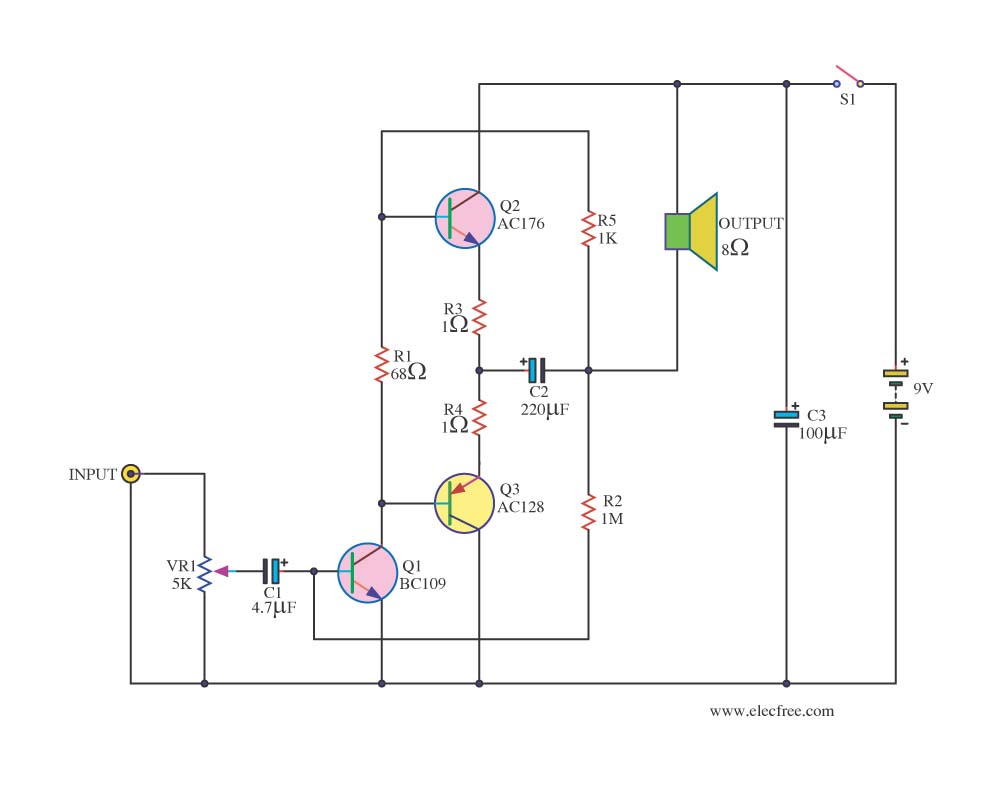
Integrated circuits (ICs) are commonly utilized in various audio amplifiers, particularly in compact circuits. While transistors are convenient alternatives, they offer several advantages, such as the ability to repurpose old equipment to create smaller circuits, which may be harder...
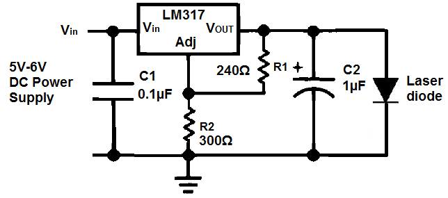
Unlike LED light, a laser's light output is more concentrated, resulting in a smaller and narrower viewing angle. This characteristic necessitates that the laser light be directed more precisely at its source for effective detection. Laser light is also...
The hardware schematic for the robotic arm, referred to as the wooden menace, is quite straightforward. The PIC microcontroller has one control line connected to each servo and also connects to an RJ45 connector, which is used to receive...
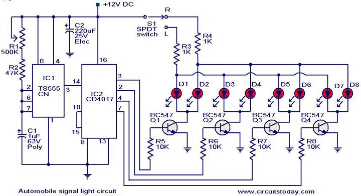
This is a simple circuit that can be used as a sequential signal light in automobiles. The circuit is based on two integrated circuits (ICs): a TS 555 CN CMOS timer IC and a CD4017 decade counter IC. The...
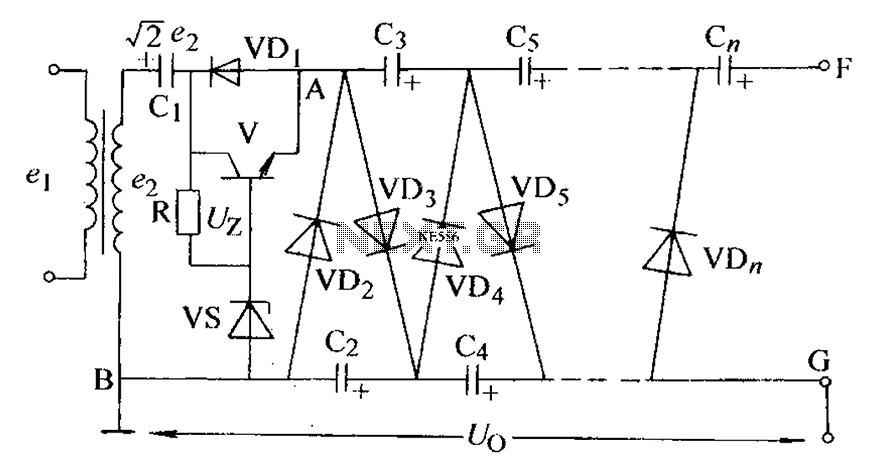
The circuit is an adjustable output voltage regulator type rectifier. It allows for obtaining peak voltage at odd multiples when the output voltage is taken from the circuit feedback (FB). Additionally, the lower point of the capacitor (CB) can...
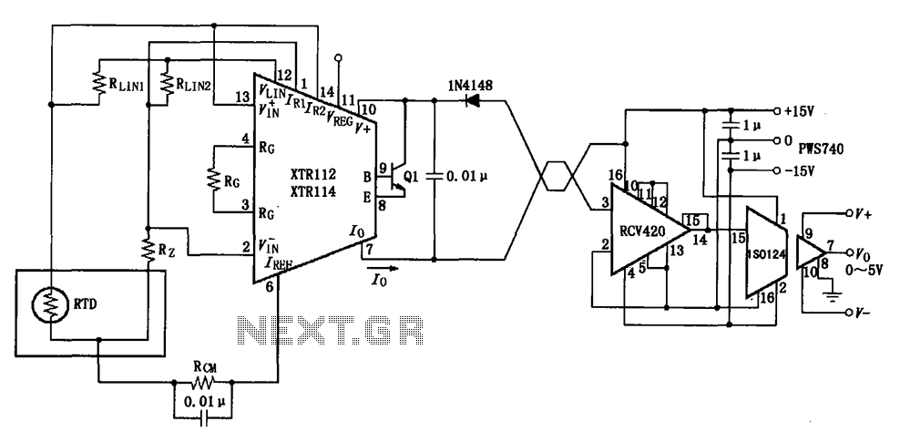
The RTD temperature data collected at the scene is converted into a voltage using the XTR112/114. This voltage is further transformed into a 4 to 20 mA current output, which is then transmitted via a twisted pair. The RCV420...
Warning: include(partials/cookie-banner.php): Failed to open stream: Permission denied in /var/www/html/nextgr/view-circuit.php on line 713
Warning: include(): Failed opening 'partials/cookie-banner.php' for inclusion (include_path='.:/usr/share/php') in /var/www/html/nextgr/view-circuit.php on line 713