
10 LED Audio Amplifier Power-meter

The circuit described serves as a power indicator for amplifiers, utilizing the LM 3915 integrated circuit (IC). This IC is designed to display the input signal level on a logarithmic scale, effectively providing a visual representation of power output in audio applications. The LM 3915 is particularly suited for this application due to its capability to drive multiple LEDs, allowing for a clear and intuitive display of power levels.
In this configuration, the circuit is directly connected to the speaker output of the amplifier, enabling it to measure power levels ranging from 0.2 watts to 100 watts. The use of a logarithmic scale is advantageous as it aligns more closely with human perception of sound intensity, making it easier for users to interpret the power output visually.
The sensitivity of the circuit can be adjusted using resistor R1, which is specified as 10 kOhm. This adjustment allows for fine-tuning of the response to different amplifier outputs, ensuring accurate readings across the specified range. The other resistors in the circuit—R2 (10 kOhm), R3 (390 Ohm), and R4 (2.7 kOhm)—contribute to setting the overall gain and stability of the circuit.
Capacitor C1, rated at 22 µF and 25V, plays a critical role in filtering and stabilizing the power supply to the LM 3915, ensuring that the IC operates reliably without fluctuations that could affect the accuracy of the readings.
The circuit is designed to accommodate ten LEDs (LED1-LED10), which can be selected in any color according to the user's preference. These LEDs serve as the visual indicators, lighting up in response to the power levels detected by the LM 3915. The arrangement of the LEDs provides a clear visual cue, with each LED representing a specific range of power output.
Overall, this power indicator circuit offers a practical solution for monitoring amplifier performance, with adjustable sensitivity and a straightforward visual output that enhances usability in audio applications.This indicator lets you see how much power an amplifier produces. The circuit uses an LM 3915, the logarithmic variation of the known IC LED VU Meter LM 3914. The circuit is connected directly to the speaker output of amplifier power and can indicate 0.2 watts to 100 watts. The sensitivity of the circuit can be varied by R1. The basic settings in the table. Parts List R1 = 10 kOhm (see text) R2 = 10 kOhm R3 = 390 ? R4 = 2.7 kOhm C1 = 22 V ?F/25 LED1-LED10 = LED (color of choice) IC1 = LM 3915 🔗 External reference
Related Circuits
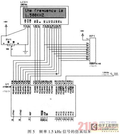
The primary function of the frequency counter is to measure the frequency and cycle of a signal. Its applications span a wide range, extending beyond simple instrument measurements to areas such as education, scientific research, high-precision instrument measurement, and...
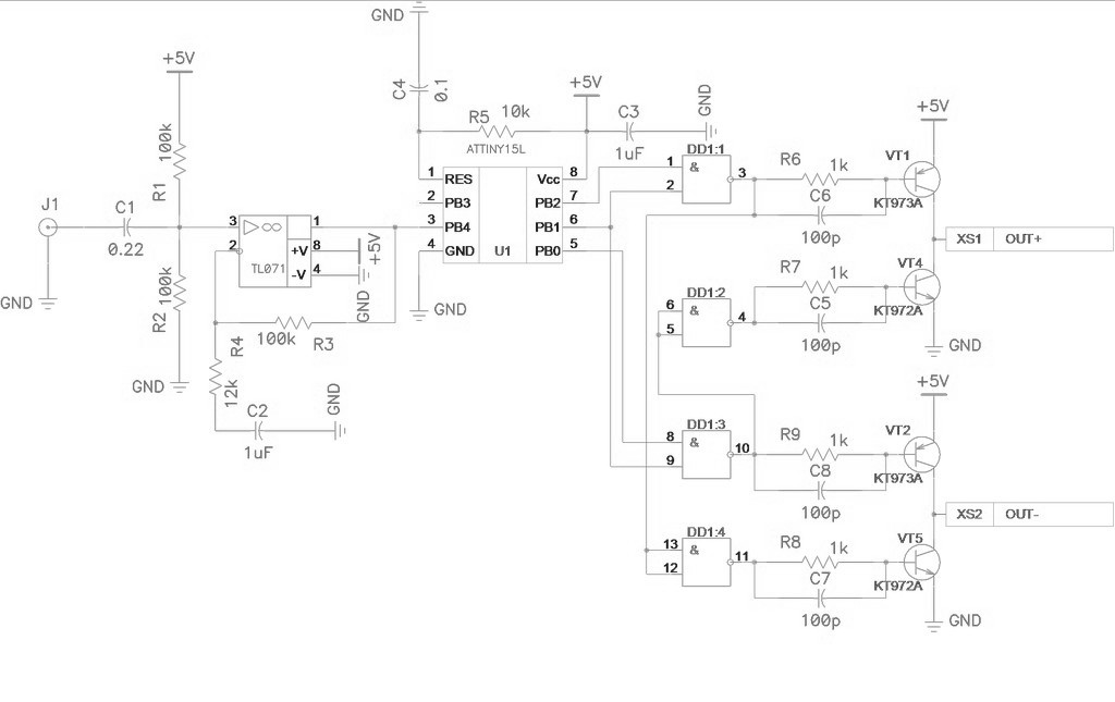
Class D amplifier circuit diagram for the ATtiny15L microcontroller. This document introduces a specific implementation of a Class D amplifier. The ATtiny15L from Atmel's AVR family is ideal for this application due to its integrated ten-bit analog-to-digital converter (ADC)...
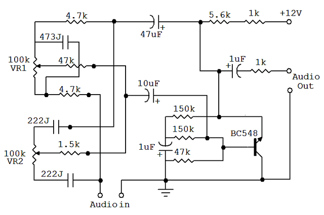
An audio equalizer circuit is utilized to modify the frequency response of an audio signal. This particular equalizer circuit is designed for adjusting the bass and treble (tone) levels of an audio amplifier. To integrate this equalizer circuit with...
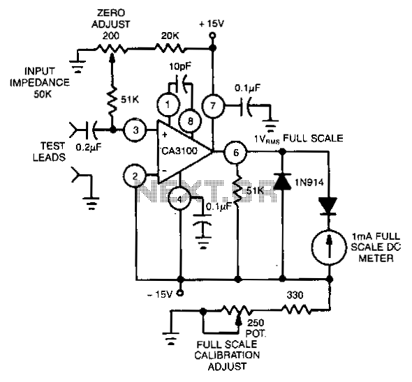
This circuit utilizes the CA3100 BiMOS operational amplifier to drive a 1-mA meter movement to its full scale with a 1-V RMS input. The circuit configuration incorporates the CA3100 BiMOS operational amplifier, which is known for its high input impedance...
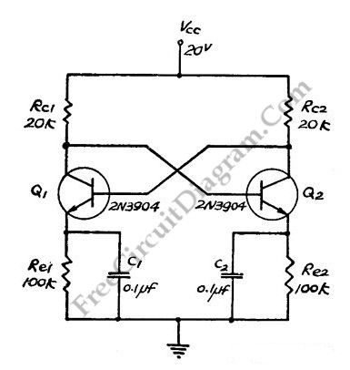
This flip-flop circuit functions as a free-running astable multivibrator, where the bases and collectors of both emitter-biased transistors are directly coupled. The switching action is facilitated by a capacitor in each emitter circuit, resulting in the generation of triangle...
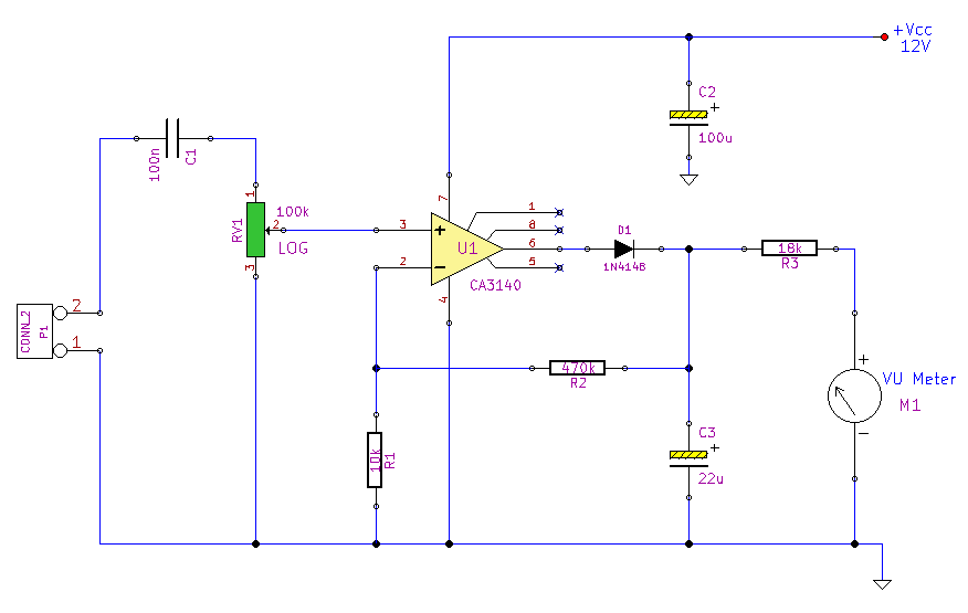
This simple circuit, designed with a minimal component count, indicates peak audio response on an analog meter, similar to a tape recorder's meter. It employs an operational amplifier configured as a non-inverting amplifier, with the addition of a diode...