
Class D amplifier for ATtiny15L

The Class D amplifier circuit utilizes the ATtiny15L microcontroller, which is designed for efficient audio amplification. The microcontroller's ten-bit ADC allows for precise audio signal sampling, while the PWM timer facilitates the conversion of the digital audio signal into an analog output through modulation techniques.
In a typical Class D amplifier configuration, the audio input signal is fed into the ADC of the ATtiny15L, where it is digitized for processing. The PWM timer generates a series of pulses that correspond to the amplitude of the input signal. These pulses are then used to drive a power stage, typically consisting of MOSFETs or transistors, which switch on and off rapidly to produce a high-efficiency output.
The output stage is designed to filter out the high-frequency switching components, leaving a clean amplified audio signal suitable for driving speakers. The design may also include feedback mechanisms to enhance stability and minimize distortion, ensuring high fidelity in audio reproduction.
Power supply considerations are critical in this design, requiring appropriate filtering and decoupling to maintain performance and prevent noise interference. Adequate heat dissipation measures should also be implemented to ensure the reliability and longevity of the amplifier circuit.
Overall, this Class D amplifier circuit diagram illustrates a compact and efficient solution for audio amplification, leveraging the capabilities of the ATtiny15L microcontroller to deliver quality sound output.Class D amplifier for ATtiny15L microcontroller circuit diagram. These units can get acquainted with one embodiment of the amplifier is Class D. Controller ATtiny15L AVR family firm Atmel is perfectly suited for this purpose, because it contains a ten-digit analog-digital converter (ADC) and a timer with a pulse-width modulator (PWM). 🔗 External reference
Related Circuits
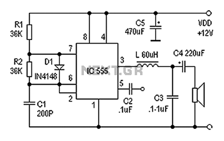
Also known as a digital amplifier, the Class-D amplifier is characterized by its compact size and high efficiency. This circuit utilizes a 555 timer IC to create a Class D amplifier. The 555 timer operates as a controllable multivibrator,...
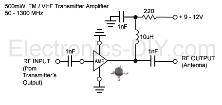
This is an aerial achievement low noise 500mW amplifier/booster designed for low power FM transmitters such as BA1404, BH1417, BH1415, and 433MHz transmitter modules. The amplifier utilizes a chip that incorporates various transistor stages and all necessary components within...
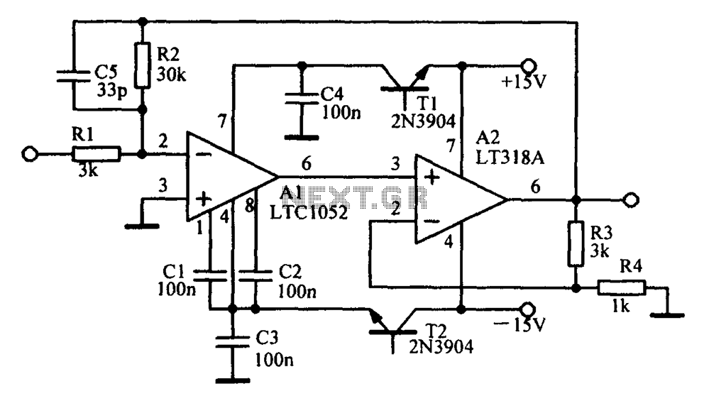
Amplifying circuit diagram to enhance the output current and voltage. An amplifying circuit is designed to increase the amplitude of an input signal, resulting in a higher output current and voltage. This type of circuit is commonly utilized in various...
The interest in tube circuits remains significant. Therefore, I will provide a comprehensive circuit of a preamplifier that is sufficiently detailed. It is primarily composed of the main preamplifier department, the input selector department, application voltage delay, and the connection...
A simple and cost-effective TV antenna amplifier circuit is constructed using the BF961, a dual-gate N-channel MOSFET, which serves as the input and mixer stages. The described TV antenna amplifier circuit utilizes the BF961 dual-gate N-channel MOSFET due to its...
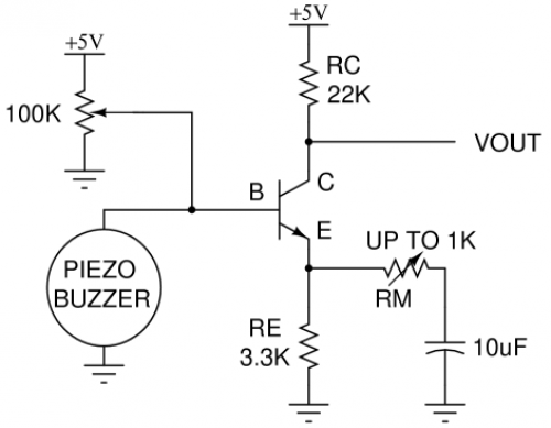
Piezo buzzers are widely used components. When disposing of an old smoke detector, it is advisable to extract the piezoelectric element for future use. Monitoring sound with a piezoelectric element can be challenging due to the low voltage it...