
Bass and Treble Controller- Audio Equalizer Circuit
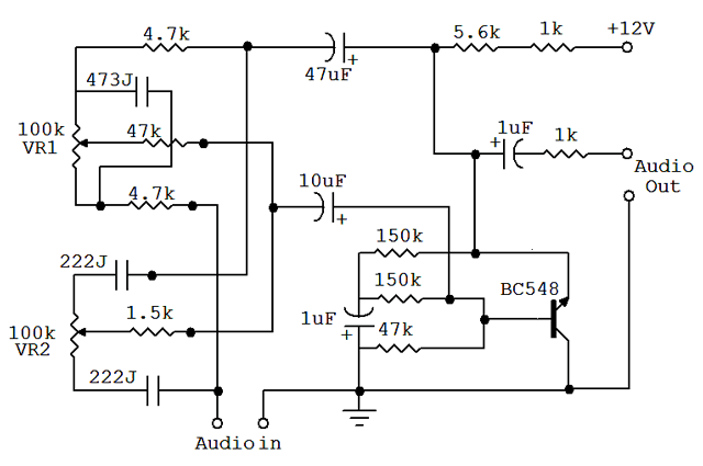
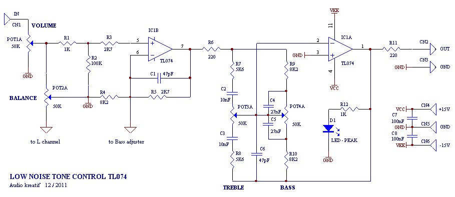
The audio equalizer circuit typically consists of a series of filters that manipulate the audio signal's frequency components. The two variable resistors, VR1 and VR2, are positioned within the circuit to function as adjustable potentiometers. These allow the user to fine-tune the audio output by varying the resistance, which in turn alters the gain of specific frequency bands corresponding to bass and treble.
The circuit may utilize operational amplifiers (op-amps) configured in a non-inverting mode to achieve the desired amplification and frequency response shaping. The design can include passive components such as capacitors and inductors to create low-pass and high-pass filters, effectively defining the cutoff frequencies for bass and treble adjustments.
The choice of a 12V power supply is significant as it aligns with the operational requirements of most audio amplification systems, ensuring compatibility and minimizing the need for additional power sources. The layout of the circuit should be optimized to reduce noise and interference, which can degrade audio quality. Shielding and proper grounding techniques are essential to maintain signal integrity.
In summary, this audio equalizer circuit is an effective tool for enhancing audio playback quality, providing users with the ability to customize their listening experience by adjusting the bass and treble levels according to personal preference. Its simplicity in design, combined with high-quality output, makes it an appealing option for audio enthusiasts and engineers alike.An audio equalizer circuit is used to adjust the frequency response of an audio signal. This is a simple equalizer circuit for controlling the bass and treble (tone) of an audio amplifier. For use this equalizer circuit in amplifier, equalizer`s output should be given in the input of amplifier. So that the main input audio signal`s bass and trebl e could be controllable before the amplify section. As shown here the bass and treble controller circuit has two variable resistor(VR1 & VR2) to control the bass and treble. VR1 for Bass Control and VR2 for Treble Control. This Bass and Treble controller circuit needed a 12Volt power supply. I would have designed it in that way because 12V is used in most of the audio amplifier circuit. and since equalizer circuit is used with audio amplifier, so there no extra power supply will required for this Equalizer.
This audio equalizer circuit is very easy to build and has a very good quality. 🔗 External reference
Related Circuits
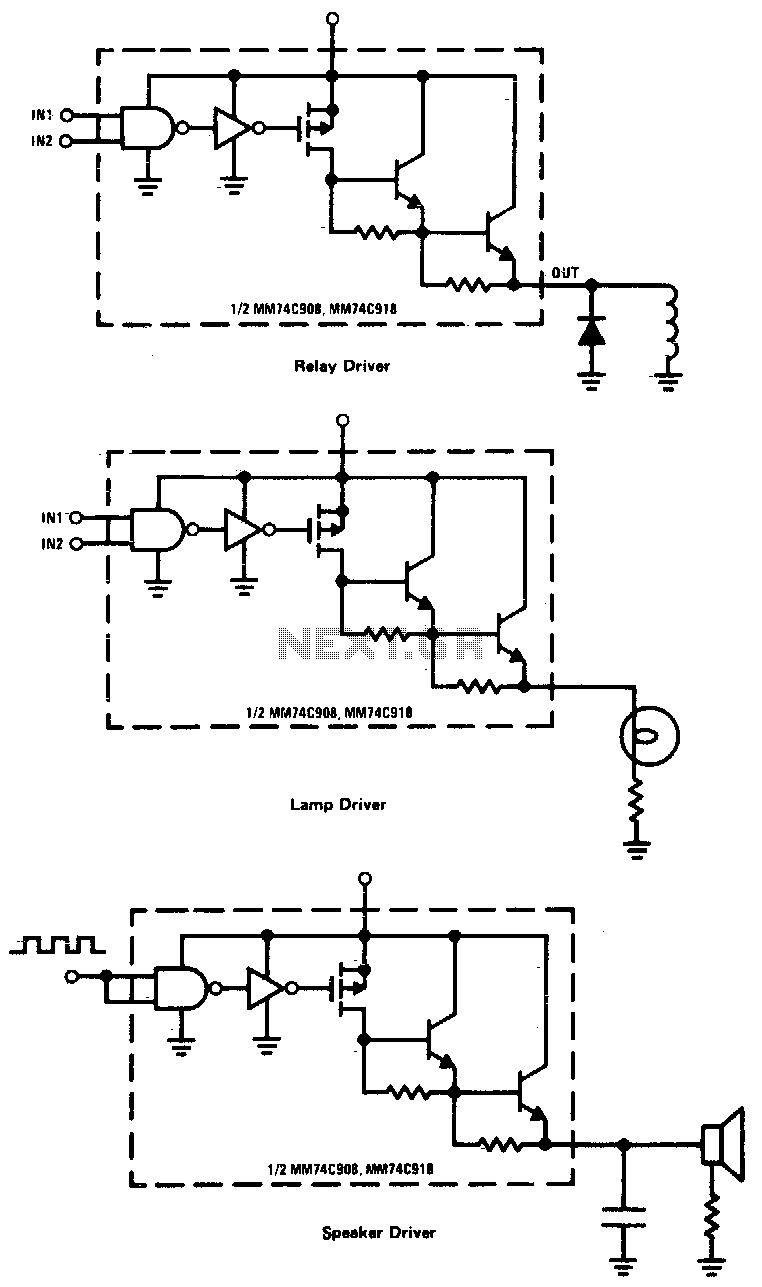
CMOS drivers for relays, lamps, speakers, and similar applications provide extremely low standby power consumption. When operating at Vcc = 15 V, the power dissipation per package is typically 750 nW when the outputs are not drawing current. Consequently,...
The following are LM555 timer circuits that have unusual functions. Designed to time a sports event; In this circuit the GREEN output is adjusted to be on for 3 minutes and then the RED output is set for 1...
This appears to be an infrared (IR) transmitter. IR signals do not penetrate walls, and it is assumed that this device is intended for use in a room separate from the one in which the user is located, rendering...
A tone control or pre-amplifier is an amplifier circuit that enhances audio signals. It is important to understand the characteristics, advantages, and disadvantages of various amplifier equipment, as the performance of different amplifiers may not show significant differences. The...
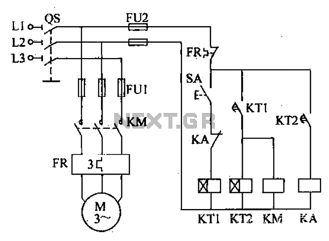
After the power switch is activated, the motor does not start immediately but instead has a specified delay period. This setup allows the machine to perform automatic intermittent lubrication control. The circuit for the motor boot delay and intermittent...
This circuit operates as a 9V DC power source supplying a 555 timer to generate a square wave. The output is then processed through a Half-Wave Series Multiplier (Villard Cascade) to achieve a high voltage DC output. The goal...
Warning: include(partials/cookie-banner.php): Failed to open stream: Permission denied in /var/www/html/nextgr/view-circuit.php on line 713
Warning: include(): Failed opening 'partials/cookie-banner.php' for inclusion (include_path='.:/usr/share/php') in /var/www/html/nextgr/view-circuit.php on line 713