
10 led VU Meter using LM3915

The circuit operates by taking an audio signal input, which is then processed through the TL071 operational amplifier configured for half-wave rectification. This configuration allows the circuit to convert the audio waveform into a unidirectional signal suitable for further processing. The output from the TL071 feeds into the LM3915, which is designed to drive a bar graph or LED display.
The LM3915 is a versatile LED driver that can be configured to operate in either bar mode or dot mode, depending on the application requirements. In this circuit, it is set to bar mode, allowing all 10 LEDs to light up in a linear fashion according to the amplitude of the incoming audio signal. The brightness of each LED corresponds to the level of the input signal, providing a visual representation of audio levels, which is particularly useful in audio equipment for monitoring purposes.
The circuit requires a power supply to operate both the TL071 and the LM3915. Typically, a dual power supply (positive and negative) is used for the TL071, while the LM3915 can operate from a single supply voltage. Proper decoupling capacitors should be placed near the power pins of both ICs to ensure stable operation and minimize noise.
Overall, this simple yet effective circuit serves as a basic VU meter, providing an intuitive visual feedback mechanism for audio signals. It is suitable for applications in audio mixing consoles, sound level meters, and other audio-related devices where monitoring signal levels is essential.Circuit diagram is a very simple circuit-level indication, with 10 Led. Used a series of half-wave rectification of precision around IC2 TL071, with a single. LM3915 IC is used to control the led, as an indicator VU Meter. LM3915 can be controlled 10 led 🔗 External reference
Related Circuits
The initial step often taken when learning about any microcontroller or embedded system is to make an LED blink. The circuit presented below illustrates the setup for interfacing an LED. Note: Due to the large dimensions of the circuit...

With a guaranteed 1 pA input bias, the ICL 8007A is ideal for use as a pH meter or for long-term sample and hold applications. The ICL 8007A is a precision operational amplifier specifically designed for low-level signal processing, making...
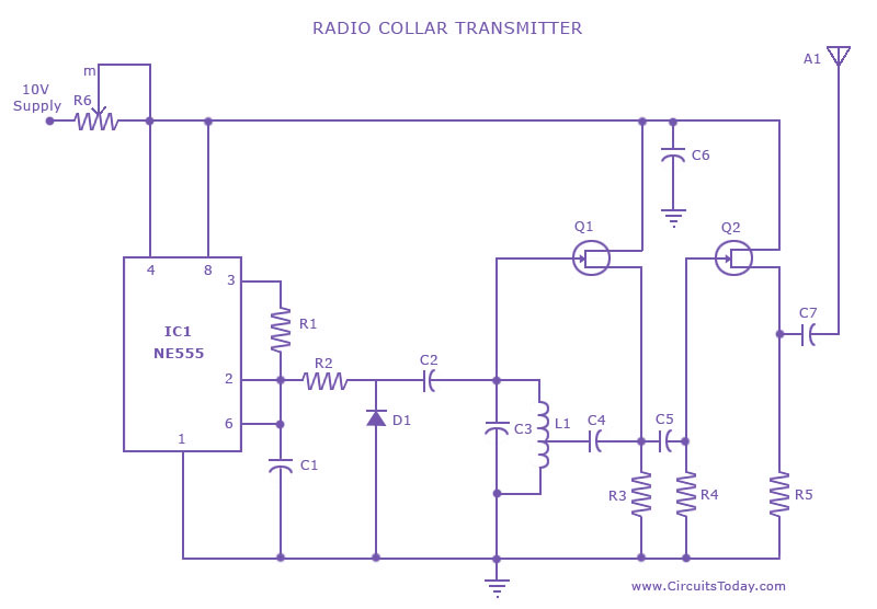
This is a radio transmitter circuit diagram designed for integration into radio collars using the NE 555 integrated circuit. The circuit transmits a pulse in the FM band, specifically between 88 MHz and 105 MHz. The radio transmitter circuit utilizes...
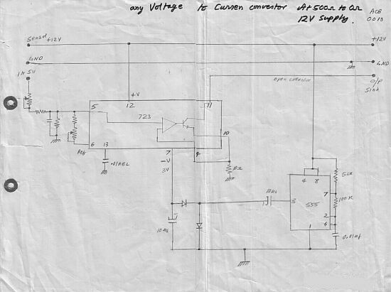
This circuit converts a voltage control output from a process controller into a current control signal, which is necessary when an AC drive or valve requires a current control signal. It operates as a three-wire voltage-to-current loop converter. A...
This meter circuit utilizes a single integrated circuit (IC) and a minimal number of external components. It displays audio levels using ten light-emitting diodes (LEDs). The input voltage can range from 12V to 20V, with a recommended voltage of...
A request has been made to design a unique outdoor Christmas decoration in the form of an LED-illuminated star. The objective is to create a very bright display using 30 ultra-bright 8mm LEDs. The plan includes sanding the domes...