
microcontroller led interfacing
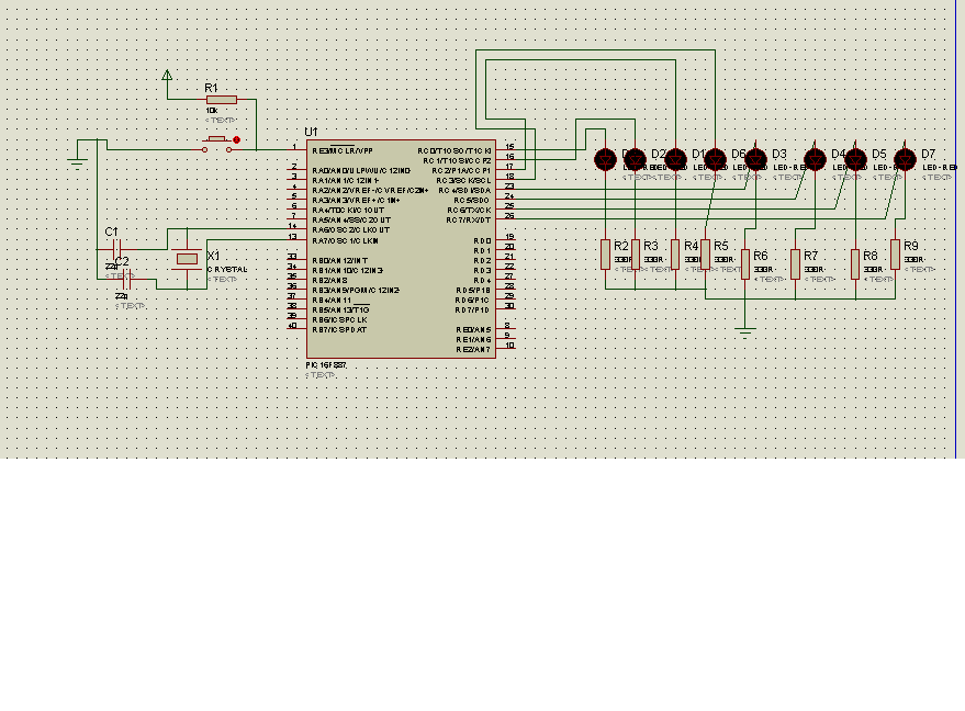
The circuit for interfacing an LED with a microcontroller typically involves a few essential components: the microcontroller itself, a resistor, and the LED. The microcontroller outputs a digital signal that can be used to control the LED. The LED is connected in series with a current-limiting resistor to prevent excessive current that could damage the LED.
In a standard configuration, the anode (longer lead) of the LED is connected to a digital output pin of the microcontroller, while the cathode (shorter lead) is connected to ground through the resistor. The value of the resistor can be calculated using Ohm's Law (V = IR), where V is the voltage drop across the resistor, I is the desired current through the LED, and R is the resistance. Typically, for a standard LED, a current of 20 mA is common, and the forward voltage drop of the LED is usually around 2V for red LEDs and 3V for blue and white LEDs.
When the microcontroller outputs a high signal (logic level '1'), current flows through the LED, causing it to illuminate. Conversely, when the output is low (logic level '0'), the LED turns off. This simple on-off control can be programmed in the microcontroller's firmware to create various blinking patterns, which serve as a fundamental exercise in understanding digital output operations.
This basic LED interfacing circuit serves as a foundational project for beginners in embedded systems, providing insights into digital control, component selection, and circuit design principles.The first thing usually done while learning any microcontroller or embedded system is blinking an LED. The circuit below shows the circuit for Interfacing an LED. note: Since the circuit diagram dimensions are big, your browser may fit the image to window size, if you are using Internet explorer, then an expander tool will be..
🔗 External reference
Related Circuits
The code in mikroC PRO for the PIC16F887 microcontroller is designed to operate with an 8.000 MHz clock frequency on a Microchip 44-pin demo board. The routines have been developed using HITECH C, but the focus is on utilizing...
Here is the schematic, PC board pattern, and parts placement for a "Fantastic Atom Expander". This circuit produces an "exploding atom" effect using 98 LEDs. The LEDs can be any colour but blue. For a very interesting effect, make...
Circuit of a crystal-controlled FM transmitter. The circuit utilizes a crystal oscillator and several power amplifier stages to enhance output power. The crystal-controlled FM transmitter circuit is designed to generate frequency-modulated signals with high stability and precision. At the core...
In the circuit, a quad voltage comparator (LM339) functions as a simple bar graph meter to display the charge condition of a 12-volt lead-acid battery. A 5-volt reference voltage is applied to each of the positive inputs of the...

Twenty-five musical keys and 25 LEDs are provided to denote F to F" with half notes in between. Memory can store a played tune. There are ten preprogrammed tunes (each has an average of 55 notes) masked in the...
The circuit is a comparator that can measure the voltage of a car battery in steps of 1 Volt. The voltage is determined after comparing the voltage of the battery, which is applied to the inverting inputs of amplifiers,...