
30 LEDs off AC mains
To construct the LED-illuminated star, a schematic circuit will be designed to accommodate 30 ultra-bright 8mm LEDs. Each LED will be connected in parallel to ensure uniform brightness across the display. The circuit will include a suitable power supply, typically a 12V DC source, which is common for LED applications.
To begin, the LEDs will be arranged in a star shape, with each LED positioned at the points of the star. The cathodes of all LEDs will be connected to a common ground, while the anodes will be connected to a resistor and then to the positive terminal of the power supply. The resistor is critical in limiting the current flowing through each LED to prevent damage. A typical forward voltage for an 8mm LED is approximately 2.0V, and the forward current is usually around 20mA.
Using Ohm’s law, the required resistor value can be calculated. For instance, if using a 12V power supply, the voltage across the resistor can be calculated as:
Voltage across resistor = Supply Voltage - (Number of LEDs x Forward Voltage)
= 12V - (30 x 2V)
= 12V - 60V (this scenario indicates a need for a different configuration since the total forward voltage exceeds the supply voltage).
In practice, it would be more feasible to use fewer LEDs in series or to use a higher voltage power supply. If using groups of 3 LEDs in series, the calculation would be:
Voltage across resistor = 12V - (3 x 2V) = 12V - 6V = 6V.
The resistor value can then be calculated using the formula:
Resistor (R) = Voltage across resistor / Current (I)
= 6V / 0.02A = 300 ohms.
A 300-ohm resistor would be suitable for each series of three LEDs.
To ensure stability and longevity of the circuit, a fuse may be added to protect against overcurrent conditions. Additionally, a switch can be incorporated into the circuit to allow for easy on/off control of the illumination.
For outdoor use, it is essential to ensure that all components are weatherproofed, either by using sealed enclosures or by applying weather-resistant coatings. Proper insulation of all connections will prevent short circuits and ensure safety during operation.
This LED star will not only serve as a unique decoration but also provide a bright and festive atmosphere for outdoor Christmas celebrations.My father-in-law wants to do something unique for his outdoor Christmas decorations and I told him Id help. He wants an LED-illuminated star to hang on his house that will be very-bright. (Of course my definition of very-bright is quite different than his) so I am thinking about 30 of those ultra-bright 8mm ebay lights would be fine.
I am going to sandpaper the domes to diffuse them and make them really stand out. Anyways, for the real question, Here is my plan for the circuit (30 leds.. 🔗 External reference
Related Circuits
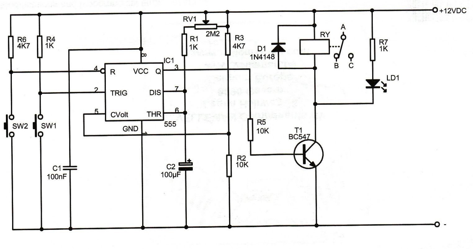
This compact design forms a remotely operated switch that receives its control signal via the mains voltage. The switch is operated using the mains remote transmitter described elsewhere in this issue. With this transmitter, a switch should be connected...
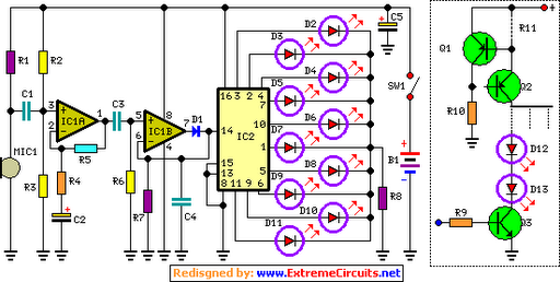
The basic circuit illuminates up to ten LEDs in sequence, synchronized with the rhythm of music or speech detected by a small microphone. The expanded version can drive up to ten strips, each consisting of up to five LEDs,...
An Xbox 360 console previously experienced a problem known as the 3 Red Lights of Death (3RLOD). To address this issue, the stock heatsinks were removed, and a Koolance external water cooling system was installed. This modification has effectively...

A circuit is needed to drive three or more LEDs at a current of 200-350mA each, with the capability to randomly flash or strobe them at a frequency of 5-20Hz. The input power should be low-voltage DC, with a...
Ensure that connections are verified against the circuit diagram and schematic provided below. This can be utilized while following the tutorial video. The circuit diagram serves as a crucial reference for accurately assembling electronic components in a project. It illustrates...
An LED, or Light Emitting Diode, is a semiconductor device that allows current to flow in one direction while blocking it in the opposite direction. This characteristic makes LEDs polarized components, having a positive side known as the anode...
Warning: include(partials/cookie-banner.php): Failed to open stream: Permission denied in /var/www/html/nextgr/view-circuit.php on line 713
Warning: include(): Failed opening 'partials/cookie-banner.php' for inclusion (include_path='.:/usr/share/php') in /var/www/html/nextgr/view-circuit.php on line 713