
10 Minute timer circuit

To design a timer circuit utilizing the NE555 IC, the monostable configuration can be implemented to achieve the desired time delay. The time delay (T) for the monostable multivibrator is calculated using the formula:
\[ T = 1.1 \times R \times C \]
Where:
- \( T \) is the time in seconds,
- \( R \) is the resistance in ohms,
- \( C \) is the capacitance in farads.
For a 1-minute delay, which is equivalent to 60 seconds, the values of R and C need to be selected accordingly. For example, if a capacitor of 100 µF is used, the resistance can be calculated as follows:
\[ R = \frac{T}{1.1 \times C} = \frac{60}{1.1 \times 100 \times 10^{-6}} \approx 545 kΩ \]
This suggests using a resistor value around 560 kΩ for practical purposes. Alternatively, if a smaller capacitor value is preferred, such as 10 µF, the resistance would need to be significantly higher:
\[ R = \frac{60}{1.1 \times 10 \times 10^{-6}} \approx 5454 kΩ \]
This indicates a resistor value of about 5.6 MΩ. It is essential to ensure that the resistor and capacitor chosen are compatible with the NE555 specifications and can handle the required voltage and current for the circuit to function effectively.
The circuit should also include a push button switch (S1) to initiate the timing sequence. Upon pressing the switch, the output pin of the NE555 will transition, activating the desired output (e.g., an LED or buzzer) after the specified delay. The output can be further modified by adding additional components such as transistors if higher current is needed for driving larger loads.
Overall, the design of the timer circuit using the NE555 IC can be tailored by selecting appropriate resistor and capacitor values to achieve the desired timing while ensuring reliable operation.When ever you need to get an alarm or intimation after ten minutes, the circuit shown below can be used. The circuit is nothing but a monostable multivibrator based on IC NE 555. When ever you press the reset push button the green LED D1 glows after 10 minutes. if i change the value like R1=9. 5k ohm, R4=2. 15M ohm, C1=3. 3 micro farad, C2=100 micro fa rad and other all values remain same then after what time diode D1 will glows and in output what will be come CAN ANY ONE HELP ME IF I WANT TO CHANGE THE 10 MINUTES TO 1 MIN WHICH COMPONENTS I HAVE TO CHANGE AND WHAT ARE VALUES FOR THE RESISTOR AND CAPACITOR FOR 1 MINUTE TIMER CIRCUIT IF U KNOW PLZZZZ MAIL TO raviteja50100@gmail. com frnds please help to me Hi Brian S1 is a push to on and release to off switch (bell push) With the first negative pulse IC pin 3 will go low, hence LED D2 Red should come on after ten minutes D1 green should come on and Red should go off.
Please check. Old post but, The schematic doesn`t work ”- There is a direct connection from positive to ground with resistors and LEDs connected. The LEDs light without any IC involvement. 100sec with 10M with 10uf or 1M with 100uF. Beyond this it cannot be predicted. but I have tried upto 470uF and 1M with a maximum of 7 to 8mts, not beyond this. I have used tantalum capacitor and metal film resistance. 100sec with 10M with 10uf or 1M with 100uF. Beyond this it cannot be predicted. but I have tried upto 470uF and 1M with a maximum of 7 to 8mts, not beyond this. I have used tantalum capacitor and metal film resistance. Dear Harley The maximum capacitance you can use is 470uF and resistance 2. 2M. with the internal leakage of 470uF, 2. 2M may not be in a position to charge the capacitor at all. hence 1M and 330uF are the practically the highest values you can use. The delay cannot be greater than 10 to 15 mts. even an hr delay is not possible. Dear Johnson you can replace the LED with an electronic music generators (similar to car reverse horn).
It is a two lead device with built in ceramic sounder and the required electronics to produce beeps or continuous tone etc. this device can operate from 3 to 15 volt with the out put sound level varying. Delete R3. Wishing you Happy construction and enjoyment. Yes it can provided you have used a NE555 chip. If you haven`t used a NE555 then if it doesn`t work its most likely the 555 can`t handle the current.
A transistor would then be required as well. Most buzzers come with a rated voltage and current. The voltage isn`t too serious as most buzzers will operate from 1. 5V 20V even if it says 5V(depending on manufacturer). If it`s a 5V buzzer it should work just as well off of 9V as off 5V. 🔗 External reference
Related Circuits
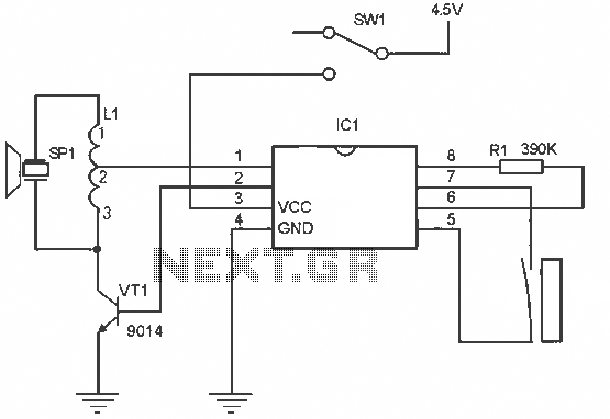
The alarm circuit operates as follows: When the power switch SW1 is turned on, the alarm system becomes active. If a magnet is brought close to the spring, the magnetic field attracts the spring, causing the dynamic and static...
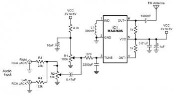
The FM transmitter circuit is built using a single MAX2606 chip. This simple FM transmitter connects a home entertainment system to a portable radio, allowing music to be played in one room and listened to in another, such as...
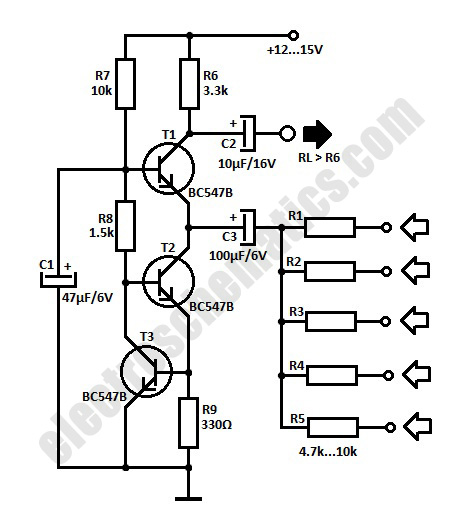
The simple audio mixer circuit is built on the common base principle, where input voltages are transformed into alternating currents which are summed to form the output. The simple audio mixer circuit utilizes a common base configuration to achieve effective...
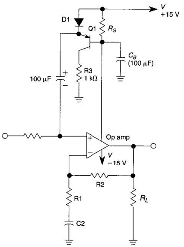
This circuit is an Automatic Gain Control (AGC) system designed for audio-frequency signals. AGC systems typically consist of three main components: an amplifier, a rectifier, and a controlled impedance. In this particular circuit, the functions of both the amplifier...
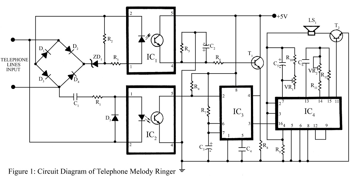
The telephone project described here is a telephone ringer that produces pleasant tunes when a call is received. The tunes generated by this telephone ringer are more melodious and soothing compared to those of traditional telephone instruments and piezo...
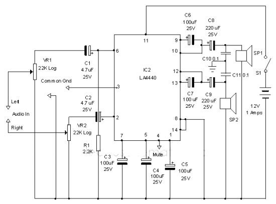
The LA4440 audio amplifier IC can be utilized to design a straightforward stereo power audio amplifier project, capable of delivering 6 watts of output power into an 8-ohm load. This audio amplifier IC features a minimal number of external...
Warning: include(partials/cookie-banner.php): Failed to open stream: Permission denied in /var/www/html/nextgr/view-circuit.php on line 713
Warning: include(): Failed opening 'partials/cookie-banner.php' for inclusion (include_path='.:/usr/share/php') in /var/www/html/nextgr/view-circuit.php on line 713