
10 STEP SEQUENCER

The analog sequencer circuit is a versatile tool for creating and manipulating musical sequences. The core of the design revolves around the CD4017 decade counter, which is pivotal in determining the sequence length and controlling the output signals. The internal clock, based on a 555 timer, offers a stable timing reference, while the external clock option provides flexibility for synchronization with other devices. This dual-clock capability enhances the sequencer's usability in collaborative settings.
The ten-step rotary switch allows for intuitive control over the sequence length, enabling musicians to customize their performance. The use of LEDs to visually indicate each step provides immediate feedback, essential for live performance scenarios. The potentiometer serves as a crucial interface for adjusting the output voltages, allowing for dynamic changes in pitch and timbre.
The inclusion of an on/off switch for each note enhances the sequencer's functionality, enabling users to create complex patterns by selectively skipping steps. The CV output jack extends the sequencer's capabilities, allowing for integration with a variety of external synthesizers and modular systems, thus broadening the range of sound design possibilities.
The CD4046 Phase-Lock Loop adds another layer of complexity, enabling the generation of audible tones directly from the sequencer's output. This feature is particularly valuable for users who wish to create sounds without the need for external instruments. The adjustable frequency range through resistor/capacitor pairing allows users to tailor the sound to their specific requirements, making the sequencer adaptable to various musical styles.
The educational aspect of the project, exemplified by the workshop at ITP Camp, highlights the importance of community engagement in the field of electronic music. By providing hands-on experience in soldering and assembly, participants gained practical skills while exploring the creative potential of analog sequencers. The positive reception and subsequent mention on the Make Blog underscore the project's impact within the DIY electronics and music communities.This analog sequencer was designed with the idea of cooperative play in mind. It can be used as a standalone instrument, or linked together with other sequencers running on the same clock speed. Mark Kleback and I were working separately working on sequencers based on Nicholis Collin`s schematics in his Handmade Electronic Music.
We were playing m usic together and we wanted to figure out a way to sync up out sequencers together simply. Very similar to what MIDI does for people`s instruments, but we wanted something much simplier and easier to build and implement. So we designed this new circuit to allow multiple sequencers to be tied together or run off a master clock.
The circuit is designed to have two different timing circuits, internal and external. The internal clock is a controllable 555 timer circuit. With a switch you can change to an external clock that can be anything from other 10 step sequencers or a master clock programmed through a microcontroller. The clock pulses the CD4017 decade counter which you can control with a ten step rotary switch. The length of the sequence can vary between 1 and 10 steps. Each step is shown visually using an LED and sent through a potentiometer to vary the voltages coming out (or rather to change the note in the sequence).
There is also an on off switch for each not if you want to skip notes in the sequence. Mark and I also added a CV output jack at the ouput of the decade counter for the user to control other instruments. Like the Realistic in the video above. However if you choose not to control an external instrument, the output of the CD4017 is routed through CD4046 Phase-Lock Loop to create audible tones.
The range of frequencies is dependent on a few resistor/capacitor pairing off the CD4046 which the user can change depending on their needs. It just so happened that ITP Camp was looking for people to help teach a workshop on sequencers. Mark and I took our schematic and designed and fabricated some printed circuit boards and put together some kits for campers.
We taught a two day workshop for the campers. The first day was scheduled as solder workshop to get the sequencers up and running, and the second day was a concert for all the sequencers together. We even got a mention on the Make Blog for our sequencer kit. We still have plenty of PCBs of the sequencer. Just send me an e-mail if you want one, and I`ll happily send it. You can even see the build instruction from the sequencer class HERE 🔗 External reference
Related Circuits
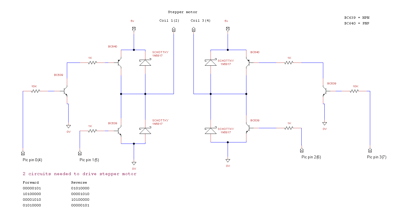
miRover. This page details how to use a PIC microcontroller and an H-bridge or an L298 to drive a bipolar stepper motor. The project involves utilizing a PIC microcontroller to control a bipolar stepper motor, which is commonly used in...
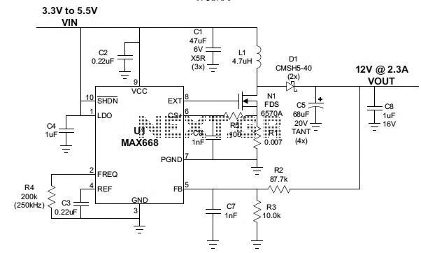
3 to 12 volts step-up DC converter using MAX668 integrated circuit design The circuit described is a step-up (boost) DC-DC converter designed to convert an input voltage in the range of 3 to 12 volts into a higher output voltage....
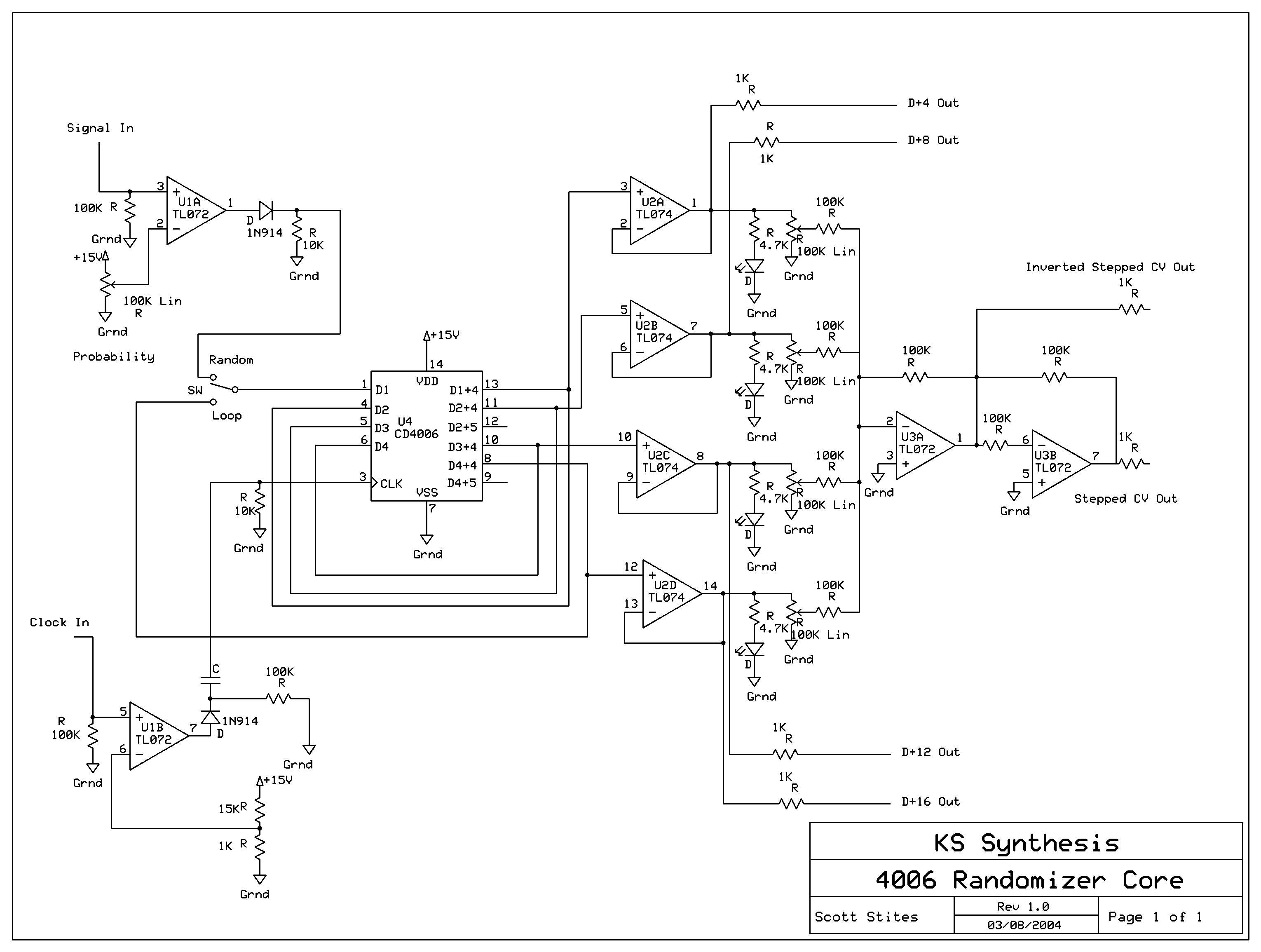
The mechanics of the Quantized Random Voltage function are intriguing. Instead of having fixed quantization steps for each output of the 4006 shift register, it is proposed to make the voltages adjustable through potentiometers. The Quantized Random Voltage function...
This circuit resembles an LED clock but utilizes 12 neon indicator lamps in place of LEDs. It operates on two high-capacity nickel-cadmium cells (2.5 volts), providing power for several weeks. A small switching power supply generates the high voltage...

The circuit diagram illustrates a simple stepper motor controller utilizing basic components. The driver circuit employs four SL100 transistors to control the motor windings, along with two NOT gates and one XOR gate to decode the two-bit control logic...
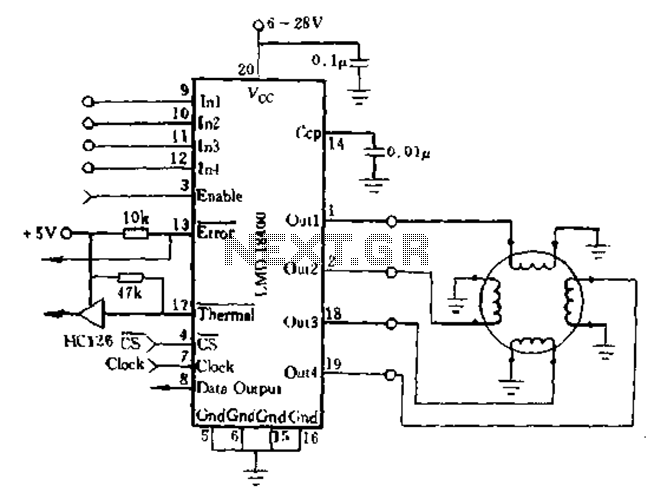
The DMOS power switch exhibits an ON-state resistance with a positive temperature coefficient, allowing for the parallel connection of four switches to increase load current, resulting in a monolithic design. The LMD18400 can drive one, two, or four small...