
10 to 15 MHz AM Transmitter Circuit
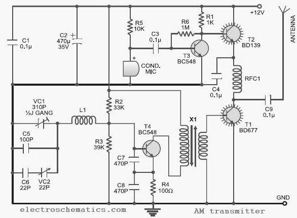
This AM transmitter circuit operates within the frequency range of 10 to 15 MHz, making it suitable for various amateur radio applications. The use of a ½J gang condenser (VC1) allows for precise tuning of the carrier frequency, while inductor L1 works in conjunction with VC1 to establish the desired frequency. The additional frequency trimming capability provided by VC2 ensures that the output remains stable and accurate.
The signal amplification is achieved through a series of transistors, starting with T4, which amplifies the carrier signal. The RF amplifier stage, based on transistor T1 (BD677), is crucial for boosting the RF signal to a level suitable for transmission. Transformer X1 plays a vital role in coupling the amplified carrier signal to the RF amplifier while providing isolation between stages.
The audio input, captured by the condenser microphone, is first preamplified by transistor T3 (BC548). This preamplification is essential for ensuring that the audio signal is strong enough for further processing. The amplified audio signal is then fed into transistor T2 (BD139), which modulates the RF signal produced by T1. The modulation process involves varying the current through T1 based on the amplitude of the audio signal, effectively encoding the audio onto the RF carrier wave.
RFC1 serves an important function in the circuit by blocking any unwanted RF signals from T2 from reaching the power supply, thereby preventing interference and ensuring stable operation of the transmitter. This design demonstrates an efficient and cost-effective approach to building an AM transmitter suitable for hobbyists and educational purposes in radio communications.This low-cost AM transmitter is tunable from 10 to 15 MHz with the help of ½J gang condenser VC1, which determines the carrier frequency of the amplitude modulation transmitter in conjunction with inductor L1. The frequency trimming can be done with VC2. The carrier is amplified by transistor T4 and coupled to RF amplifier transistor T1 BD677 thr ough transformer X1. The AM radio transmitter does not use any modulator transformer. The audio output from condenser MIC is preamplified by transistor T3 (BC548). The audio output from T3 is further amplified by transistor T2 (BD139), which modulates the RF amplifier built around transistor T1 by varying the current through it in accordance with the audio signal`s amplitude. RFC1 is used to block the carrier RF signal from transistor T2 and the power supply. 🔗 External reference
Related Circuits
The configuration presented in the diagram below is a simple MOSFET-based design intended for amplifying current at ±60 volts, allowing the connected transformer to generate a required output of 1 kVA. The components Q1 and Q2 form the initial...
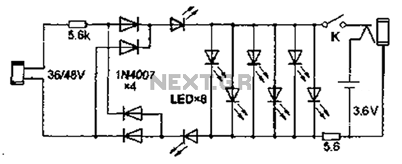
Also known as the Free lamp (commonly referred to as the Myanmar lamp by online sellers), this device operates using the voltage from a standard household fixed telephone line, eliminating the need for batteries or AC power. The lamp...
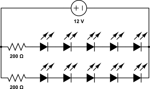
A 12V power supply is available, and there is a need to power LEDs with a forward voltage of 2V. It is questioned whether only six LEDs can be powered or if the cathode of one LED can be...

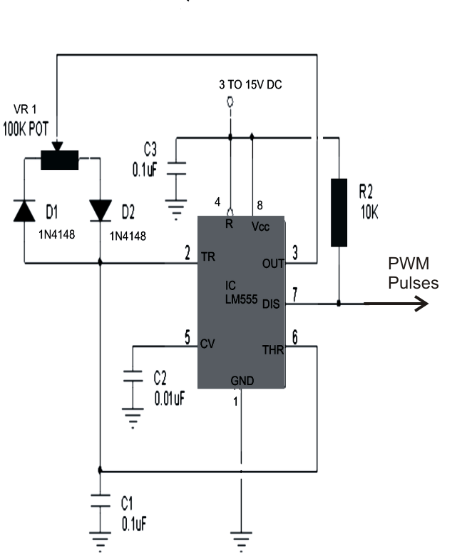
This 555 timer circuit temperature monitoring system project can monitor temperature at up to four points. The system allows for the selection of whether the alarm should be triggered when the temperature increases or decreases, depending on the resistance...

This circuit is a graphic equalizer that can be built with a low component count and is controlled using the LA3600 single IC chip. The internal design of the chip utilizes a transistor gyrator circuit, with connections to external...
The monostable 555 timer multivibrator circuit, also known as a one-shot monostable multivibrator, functions as a retriggerable pulse generator. The term "monostable" indicates that the circuit has only one stable state, with the unstable state referred to as the...
Warning: include(partials/cookie-banner.php): Failed to open stream: Permission denied in /var/www/html/nextgr/view-circuit.php on line 713
Warning: include(): Failed opening 'partials/cookie-banner.php' for inclusion (include_path='.:/usr/share/php') in /var/www/html/nextgr/view-circuit.php on line 713