
Make This 1KVA (1000 watts) Pure Sine Wave Inverter Circuit
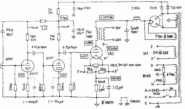
The described circuit employs a MOSFET configuration to achieve efficient amplification of the input signal. The differential amplifier stage (Q1 and Q2) plays a crucial role in increasing the voltage of the input sine wave, preparing it for the subsequent driver stage. This stage, consisting of MOSFETs Q3, Q4, and Q5, is responsible for the push-pull operation, which alternates the current through the transformer. The push-pull arrangement is essential for maintaining balance and efficiency in the circuit, ensuring that the transformer receives the full 60 volts required for optimal performance.
The transformer is designed to convert the amplified electrical energy into usable AC power, specifically targeting a 1 kVA output. The frequency of operation, set at 50 Hz, aligns with standard mains frequency, making the system suitable for typical power applications. The sine wave generator circuit, crucial for providing the necessary input signal, employs operational amplifiers to shape the waveform. Careful selection of passive components within this circuit is vital to ensure that the output closely resembles a pure sine wave.
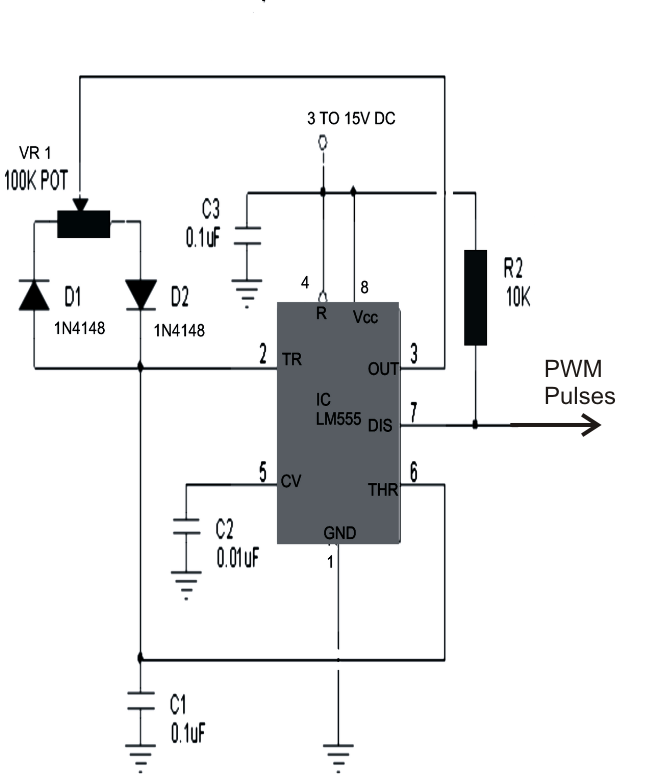
To mitigate the heating issues associated with the exponential output of the sine wave generator, the integration of a PWM circuit is recommended. PWM, or Pulse Width Modulation, allows for the generation of a signal that can effectively emulate a sine wave while minimizing heat generation in the MOSFETs. This approach not only enhances the efficiency of the inverter circuit but also prolongs the lifespan of the components by reducing thermal stress.
In summary, the presented MOSFET-based inverter circuit is a robust solution for converting DC power from batteries into a stable AC output. The careful design of the amplifier stages, transformer coupling, and sine wave generation ensures that the system operates efficiently and reliably within the specified parameters.As can be seen in the first diagram below, the configuration is a simple mosfet based designed for amplifying current at +/-60 volts such that the connected transformer corresponds to generate the required 1kva output. Q1, Q2 forms the initial differential amplifier stage which appropriately raises the 1vpp sine signal at its input to a level whic
h becomes suitable for initiating the driver stage made up of Q3, Q4, Q5. The mosfets are also formed in the push pull format, which effectively shuffles the entire 60 volts across the transformer windings 50 times per second such that the output of the transformer generates the intended 1000 watts AC at the mains level. For acquiring the intended pure sine wave output, a suitable sine input is required which is fulfilled with the help of a simple sine wave generator circuit.
It is made up of a couple of opamps and a few other passive parts. It must be operated with voltages between 5 and 12. This voltage should be suitably derived from one of the batteries which are being incorporated for driving the inverter circuit. The below given diagram shows a simple sine wave generator circuit which may be used for driving the above inverter circuit, however since the output from this generator is exponential by nature, might cause a lot of heating of the mosfets.
A better option would be to incorporate a PWM based circuit which would supply the above circuit with appropriately optimized PWM pulses equivalent to a standard sine signal. 🔗 External reference
Related Circuits
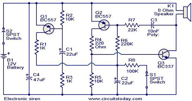
This is a compact electronic siren circuit based on three transistors. This circuit is suitable for incorporation with other alarm or siren projects such as burglar alarms, automatic factory sirens, or a simple push-to-on alarm. The electronic siren circuit...
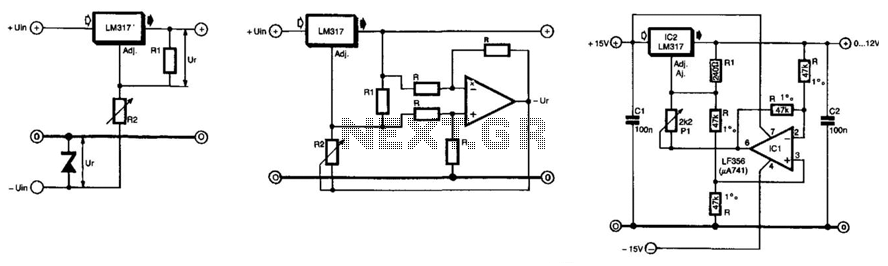
The unique feature of this regulator is that the output voltage can be adjusted down to 0 V. The regulation is provided by an integrated regulator type LM317. Typically, in supplies that can be adjusted to 0 V, this...
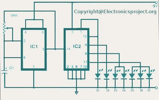
The LED indicator in this project can be used for bike indicators or car direction indicators. A 555 timer and a BCD 7490 are utilized along with several resistors, exceeding 100 in total across various electronic projects. The circuit employs...

The circuit consists of eight cascaded identical cells, each cell being a DC-controlled active phase shifter. Since the DC control is common for all shifters, the circuit is adjusted by tuning resistor RA so that the phase difference between...
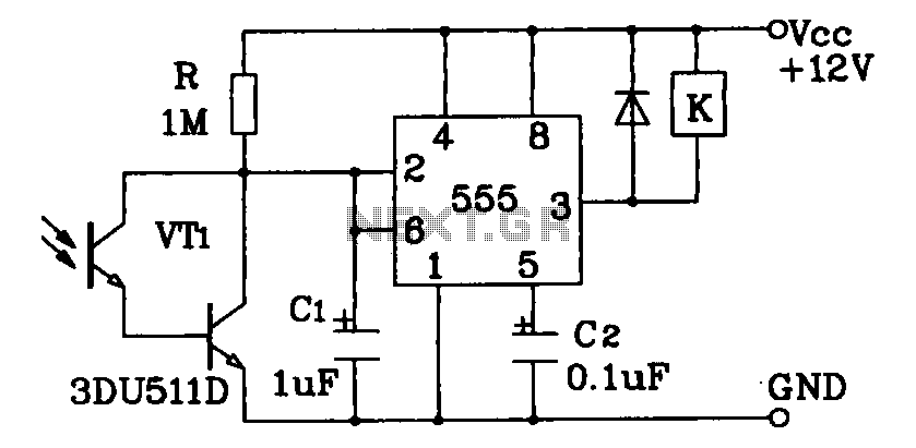
Darlington phototransistor type light-sensitive switch control circuit application. The Darlington type phototransistor serves as a sensitive element, capable of detecting low light levels for the detection of reflected light signals. The Darlington phototransistor circuit utilizes a pair of transistors configured...
This instructable will demonstrate how to interpret various circuit diagrams and assemble circuits on a breadboard. The process of reading circuit diagrams involves understanding the symbols and connections that represent electronic components and their interrelations. Key components include resistors, capacitors,...