
Monostable 555 Multivibrator Working Principle and Circuit diagram with Animation
The monostable 555 timer circuit is typically configured with a few essential components: the 555 timer IC, a resistor (R1), a capacitor (C1), and a push-button switch for triggering. The circuit operates in a manner where the capacitor C1 is initially discharged. When the push-button switch is pressed, it momentarily connects pin 2 (the trigger pin) to ground, causing the voltage at this pin to drop below the 1/3 Vcc threshold. This triggers the 555 timer to switch its output (pin 3) to a high state.
The resistor R1 and capacitor C1 together define the timing characteristics of the circuit. The time constant, which dictates how long the output remains high, is calculated using the formula T = 1.1 * R1 * C1. During the pulse duration, the capacitor C1 begins to charge through R1. The charging curve follows an exponential rise, and the output remains high until the voltage across C1 reaches 2/3 Vcc. At this point, the internal flip-flop of the 555 timer is reset, causing the output to return to a low state and the capacitor to begin discharging.
The 555 timer can be retriggered while the output is high; pressing the push-button switch again will restart the timing cycle, which is particularly useful in applications requiring pulse repetition. The circuit can be employed in various applications such as timers, pulse-width modulation, and event counters, illustrating its versatility and effectiveness in generating precise timing signals. The monostable 555 timer circuit is a fundamental building block in electronics, providing reliable and adjustable timing solutions across numerous projects and applications.Monostable 555 timer multivibrator circuit (one shot monostable multivibrator) is a retriggerable mono shot pulse generator. The name Mono stable` indicates that it has only one stable state. The unstable state is called Quasi stable state`. The duration of stable state or the pulse width is determined by the charging time constant of the RC netwo
rk. We can transfer the multivibrator from stable state to quasi stable state by using push button trigger switch. The animated (simulated) working of the mono stable 555 multivibrator is shown in this article. You can use our monostable 555 timer calculator tool to find the duration of pulse(width) easily. As we know, when the voltage at the second pin of 555 IC goes below 1/3 Vcc, the output becomes high.
This high state is known as Quasi stable state`. (Refer Astable multivibrator using NE 555 ) Then the discharge transistor is cut off and capacitor starts charging towards Vcc (Refer the internal circuit below). Charging of capacitor is through the resistor R1 with a time constant R1C1. As the capacitor voltage increases and finally exceeds 2/3 Vcc, it will reset the internal control flip flop, there by turning off the 555 timer IC (more than 2/3 voltage at the threshold pin (6th pin) causes IC to reset).
🔗 External reference
Related Circuits
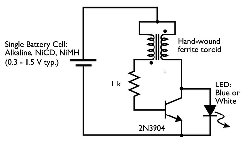
This circuit is commonly referred to as a Joule Thief, and it has been frequently encountered in various electronics videos on YouTube. The Joule Thief is a simple, low-cost circuit designed to extract energy from a single-cell battery, particularly when...
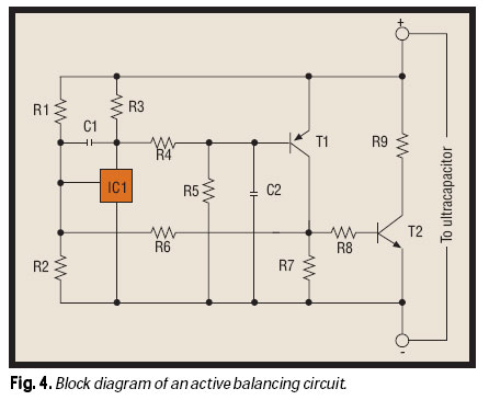
As the market seeks lighter, more compact wireless and portable devices with innovative features packed into increasingly constrained spaces, there is a concurrent pursuit for the next power supply innovation—a powerful, compact, long-lasting, economical, and safe battery. Although advancements...
These devices are low-cost, high-speed, dual JFET input operational amplifiers featuring an internally trimmed input offset voltage (utilizing BI-FET II technology). They require low supply current while maintaining a large gain-bandwidth product and fast slew rate. Additionally, well-matched high-voltage...
To measure the input impedance of an unknown circuit, first set the signal generator to a current source with a magnitude of 1 amp. A shunt resistor of 100 megohms is also required. This setup is beneficial for measuring...
Similar to the CMOS-based touch switch available on this site, this transistor-based touch switch can activate a load simply by the user touching a metal plate. It is designed to directly switch a relay, allowing it to be used...
The circuit is designed to facilitate the teaching of color synthesis principles in color television, allowing students to better understand the concept through visual aids. It effectively reproduces color signals, thus simplifying the abstract nature of color synthesis. The...