
10 To 1Hz Timebase Circuit

The MM5369 is a versatile timing generator IC that is commonly used in applications requiring precise frequency generation. In this circuit, the MM5369 is configured to accept a 3.579 MHz input from a parallel-mode crystal, which is known for its stability and accuracy in generating timing signals. The crystal oscillator circuit is essential for ensuring that the frequency remains stable over varying temperature and voltage conditions.
The output from the MM5369 is a 60 Hz square wave signal, which serves as a reliable clock source for further frequency division. The subsequent components, F8 and V9, function as frequency dividers. F8 reduces the 60 Hz signal to a 10 Hz signal, while V9 further divides the 10 Hz signal down to a 1 Hz output. These divisions are typically accomplished using flip-flops or counters, which take advantage of the square wave characteristics of the input signal.
The choice of the 3.579 MHz crystal (Y1) is critical, as it directly influences the precision of the derived signals. This frequency is commonly used in television applications, making the MM5369 an ideal choice for synchronization tasks in video equipment or related electronic systems. The design ensures that the output frequencies are stable and suitable for applications such as timing circuits, clock generation, and other digital signal processing tasks.
Overall, this circuit exemplifies a straightforward yet effective method for generating low-frequency signals from a high-frequency crystal oscillator, leveraging the capabilities of the MM5369 IC and the inherent stability of the selected crystal. This system uses an MM5369 IC to derive a 60-Hz signal from a TV burst crystal (3579 MHz). F8 and V9 producc a 10-Hz and 1-Hz signal from this 60-Hz signal. Y1 can be any parallel-mode 3.579-MHz crystal. 🔗 External reference
Related Circuits
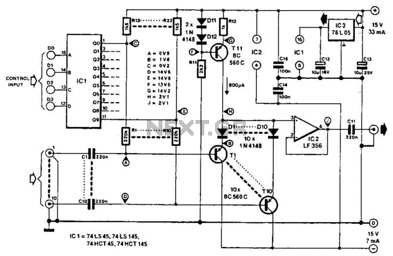
This circuit employs switched emitter followers instead of conventional analog switch CMOS chips, resulting in a more effective reduction of crosstalk between channels. It can manage up to 4 Vms with less than -80 dB crosstalk. The circuit design utilizes...
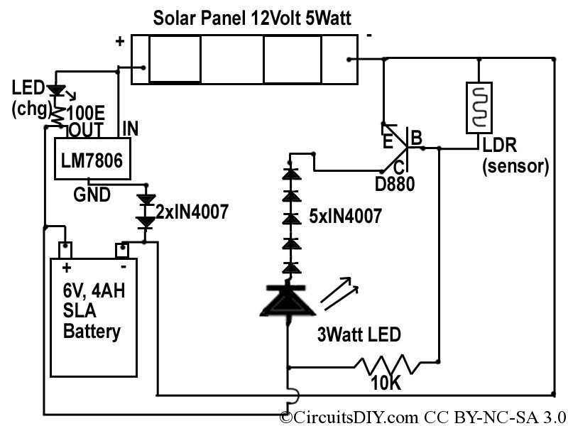
This document discusses a simple solar LED circuit. Solar panels range from 12 volts and 3 watts to larger sizes. To store energy, a 12-volt battery is required. The preferred choice is a sealed lead-acid (SLA) sealed maintenance-free (SMF)...
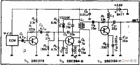
The circuit functions as a frequency modulation (FM) transmitter that operates within the 76 to 90 MHz FM radio band, commonly referred to as a wireless microphone. It receives signals through an FM radio receiver. The circuit is capable...
Unfortunately, there is no breadboard available for testing; however, modifications can be made to the PCB. The 1K potentiometer has been removed until the strobe functionality can be established. The circuit in question appears to involve a strobe light mechanism,...
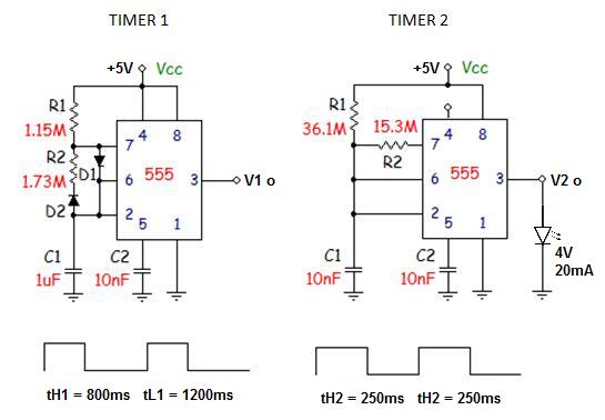
This circuit employs an astable multivibrator to alter the state of a signal based on specific conditions. It also incorporates a flip-flop, which retains the state of the output once a change is detected, completing a cycle of the...
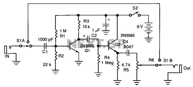
Twang is a guitar sound that closely resembles that of a banjo or mandolin. The circuit generates distinctive sounds from a standard electric guitar by eliminating the bass frequencies, heavily distorting the midrange and treble frequencies, and subsequently amplifying...
Warning: include(partials/cookie-banner.php): Failed to open stream: Permission denied in /var/www/html/nextgr/view-circuit.php on line 713
Warning: include(): Failed opening 'partials/cookie-banner.php' for inclusion (include_path='.:/usr/share/php') in /var/www/html/nextgr/view-circuit.php on line 713