
10 W AUTO ALARM SIREN
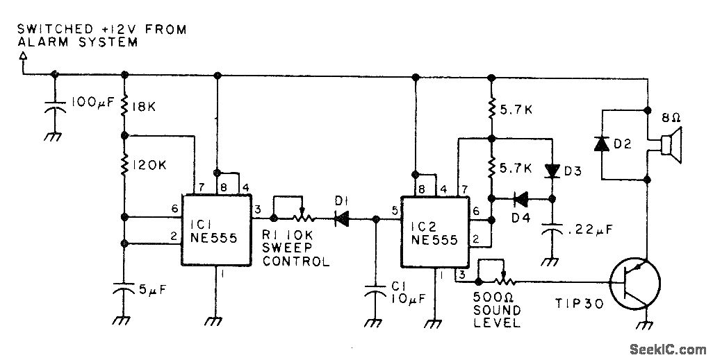
The described circuit is designed to enhance vehicle security by creating an audible deterrent. The high-intensity sound is generated through a square-wave oscillator, which is modulated to produce a sweeping frequency effect. This modulation is essential for creating a disorienting sound field that can effectively discourage potential intruders.
The triangle waveform, produced by the resistor R1, diode D1, and capacitor C1, is crucial for the modulation process. This configuration allows for a gradual increase and decrease in frequency, resulting in a sound that can be both alarming and painful to the ears when experienced at close range. The removal of capacitor C1 would result in a more traditional two-tone siren sound, which may be more legally acceptable in certain jurisdictions.
The circuit's output is designed to drive a horn loudspeaker that is capable of handling up to 10 watts, ensuring that the sound produced is sufficiently loud to be effective in deterring theft. The choice of D2 as a silicon rectifier rated at 1 A and 50 PIV indicates a reliable component capable of handling the necessary current and voltage levels without failure. The use of general-purpose silicon diodes for other parts of the circuit further enhances reliability and performance.
Overall, this circuit design presents a practical solution for vehicle security by leveraging sound as a deterrent, utilizing well-established electronic components and configurations to achieve its intended purpose effectively.Generates force field of high-intensity sound inside car, painful enough to discourage thief from entering car after tripping alarm switch by opening door. Circuit produces square-wave output that sweeps up and down in frequency. Modulation is provided by triangle waveform generated by R1, D1, and C1. If sweep-frequency siren is prohibited, remove C1 to produce legal two-tone sound. Use efficient horn loudspeaker capable of handling up to 10W. D2 is silicon rectifier rated 1 A at 50 PIV. Other diodes are general-purpose silicon. -A. T. Roderick III, New Protection for Your Car, 73 Magazine, March 1978, p 76-77. 🔗 External reference
Related Circuits
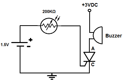
This circuit activates an alarm when it detects a specific level of light. When the light exposure increases beyond a predetermined threshold, a loud buzzer sounds, providing an alert. The alarm remains inactive in low-light conditions but triggers in...
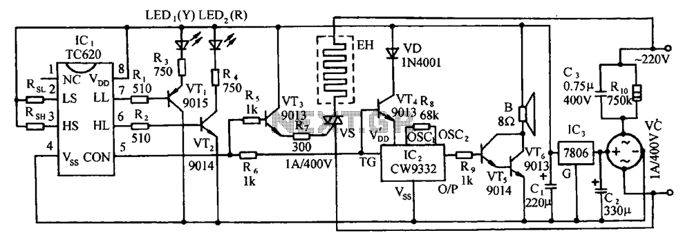
The circuit includes the TC620 temperature control circuit, the temperature indicator circuit, a thyristor-controlled heating circuit, a vocal music buck rectifier circuit, and the AC circuit. The TC620 temperature control circuit is designed to regulate temperature by monitoring the temperature...
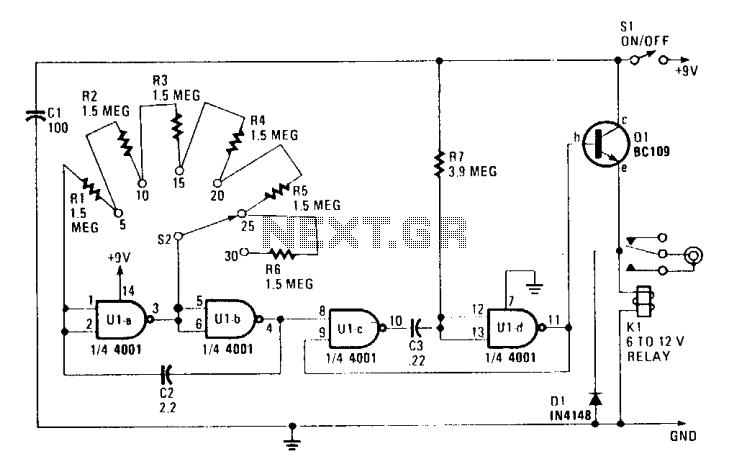
The circuit is constructed using a 4001 quad two-input NOR gate, allowing for switch-selectable auto-advance times of 5, 10, 15, 20, 25, or 30 seconds through the remote control socket of a projector. Ula and Ulb create an astable...
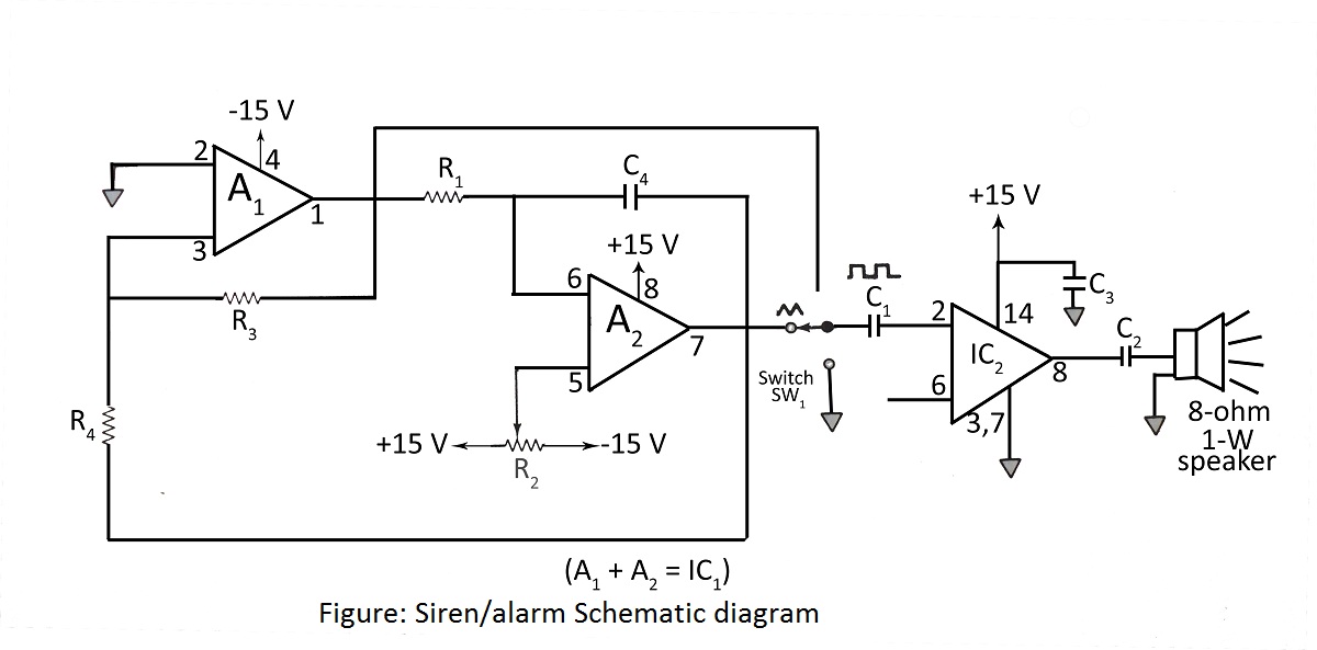
A simple siren or alarm circuit utilizing the MC1458 dual op-amp and the audio power amplifier LM380 is presented. The circuit diagram includes various configurations for sirens, doorbells, and alarm systems, along with a comprehensive parts list. The circuit operates...

Autodyne is a term used to describe a heterodyne radio device where a single tube functions simultaneously as both an oscillator and a detector. The autodyne radio circuit is a specialized design that combines the functions of signal generation and...
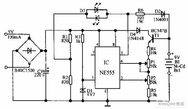
An automatic Ni-Cd battery charger circuit is depicted in the provided image. The internal comparator of the NE555 timer is configured to a reference voltage of 4.7V using a Zener diode. When the voltage at pin 6 exceeds this...
Warning: include(partials/cookie-banner.php): Failed to open stream: Permission denied in /var/www/html/nextgr/view-circuit.php on line 713
Warning: include(): Failed opening 'partials/cookie-banner.php' for inclusion (include_path='.:/usr/share/php') in /var/www/html/nextgr/view-circuit.php on line 713