
100 Mhz frequency period counter
TTL multiplexers, such as the 74LS153 or 74LS251, may also be applicable; however, additional circuitry is necessary to convert the digital output to levels compatible with TTL logic.
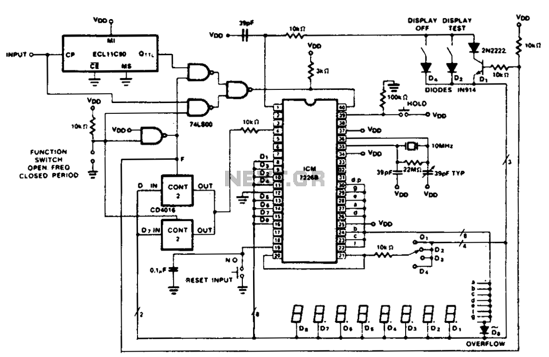
The CD4016 analog multiplexer is a versatile component that allows for the efficient selection of multiple analog signals based on digital control inputs. Its design as a transmission gate provides low on-resistance and minimal signal distortion, making it suitable for applications requiring high fidelity in signal transmission. The absence of level shifting requirements simplifies integration with digital circuits, as it can directly handle the output from various digital logic families without additional components.
When considering the use of CD4051 or CD4052 multiplexers, it is important to note their capability to manage multiple analog inputs, which can be particularly advantageous in complex systems where multiple signals need to be processed. The ability to select between 2 or 3-bit digital inputs allows for flexible configurations, accommodating different system requirements.
In applications where a microprocessor is employed, the integration of these multiplexers can streamline the design by centralizing control and reducing the need for manual switch inputs. This enhances the overall reliability and responsiveness of the system, as the microprocessor can dynamically adjust the selected input based on operational conditions or user requirements.
For scenarios that involve TTL multiplexers, such as the 74LS153 or 74LS251, it is critical to incorporate additional circuitry to ensure that the output levels are compatible with TTL logic. This may involve using level shifters or buffer circuits to adapt the output signals accordingly, thereby facilitating seamless communication between different logic families within the system.
Overall, the choice of multiplexer—be it analog or TTL—should be guided by the specific requirements of the application, including signal integrity, control complexity, and compatibility with existing digital logic.The figure shows the use of a CD4016 analog multiplex to multiplex the digital outputs back to the FUNCTION input. Since the CD4016 is a digitally controlled analog transmission gate, no level shifting of the digit output is required.
The CD4051's or CD4052's could also be used to select the proper inputs for the multiplexed input on the ICM7226 from 2 or 3 bit digital inputs. These analog multiplexers may also be used in systems in which the mode of operation is controlled by a microprocessor rather than directly from front panel switches.
TTL multiplexers such as the 74LS153 or 74LS251 may also be used, but some additional circuitry will be required to convert the digit output to TTL compatible logic levels. 🔗 External reference
Related Circuits
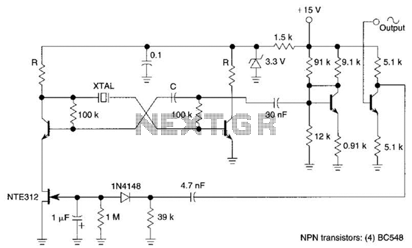
Q1, Q2, and the associated circuitry constitute a modified astable multivibrator where the loop gain is automatically adjusted to the threshold of oscillation by field effect transistor Q3. Q4 amplifies the signal at the collector of Q2 and isolates...
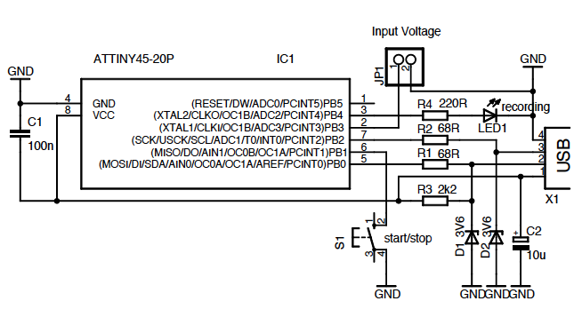
A wide range frequency meter is a useful tool for an electronics lab. This project describes a frequency meter based on the AT90S231 microcontroller that can measure input frequencies up to 50 MHz. The measured frequency is displayed on...
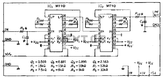
To create a Butterworth low-pass filter with a 12 dB/octave roll-off, four second-order (12 dB/oct) filter blocks are connected in series. This configuration is intended to achieve flat response characteristics across the frequency spectrum. The values for each stage...
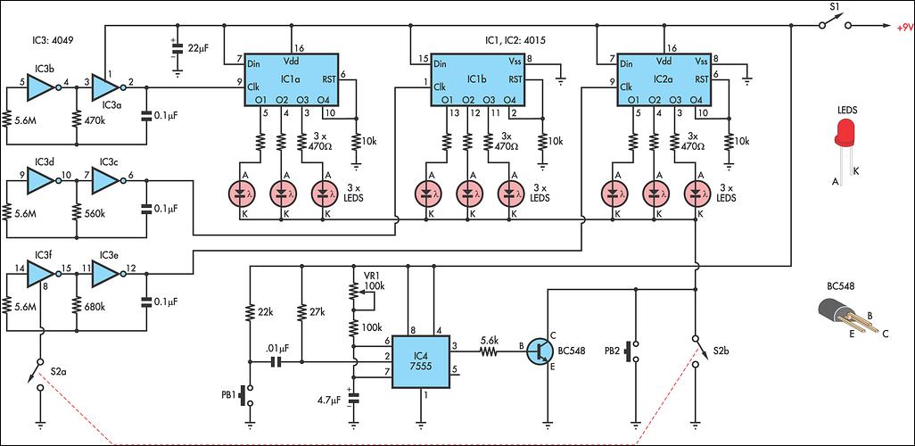
This circuit is designed as a toy to help young children learn to count. The power is activated by switch S1, and then switch S2 is closed, causing nine LEDs to flash slowly. When S2 is opened, the LEDs...
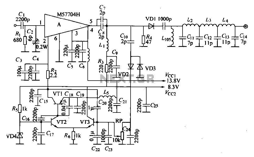
The FM radio transmitter is a high-frequency amplifier circuit that utilizes the Mitsubishi frequency set, specifically the M57704H discharge path. It operates within the frequency range of 457-458 MHz and has a transmission power of 5 watts. As illustrated...
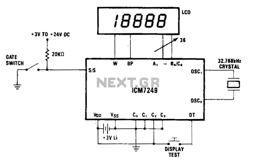
The display indicates each increment. In mode 2, external debouncing of the gate switch is unnecessary, provided that the switch bounce duration is less than 35 ms. The 3 V lithium battery can be replaced without interrupting operation if...