
Attendance counter
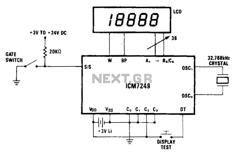
The circuit described operates with a display that increments based on input signals. In mode 2, it effectively eliminates the need for external debouncing circuitry for the gate switch, assuming the switch bounce duration is below 35 ms. This feature simplifies the design and reduces component count, making the circuit more efficient.
The power supply for the circuit is a 3 V lithium battery, which can be replaced without disrupting the operation of the display. This is achieved by using a capacitor connected in parallel with the battery. The capacitor serves as a temporary power source, allowing the circuit to remain powered while the battery is being replaced. It is crucial to select a capacitor with adequate capacitance to ensure that it can store sufficient charge for the time required to replace the battery.
A 100 µF capacitor is specified, which, when charged to 3 V, can deliver a current of 1.0 µA for approximately 50 seconds before its voltage drops to the minimum operating threshold of 2.5 V for the ICM7249 integrated circuit. This ensures that the display remains operational during the battery replacement process.
To implement this procedure correctly, the capacitor should be connected across the VDD and GND terminals before the battery is removed. This connection allows the capacitor to start discharging and providing power to the circuit immediately after the battery is disconnected. Once the new battery is installed, the capacitor can be safely removed, and the display can be reconnected to the circuit.
This design approach enhances reliability by allowing for maintenance without complete power loss, thereby preventing data loss or operational interruptions during battery changes. It is recommended to ensure that the capacitor is properly rated for the application to avoid any potential damage to the circuit components.The display shows each increment. By using mode 2, external debouncing of the gate switch is unnecessary, provided the switch bounce is less than 35ms. The 3 V lithium battery can be replaced without disturbing operation if a suitable capacitor is connected in parallel with it.
The display should be disconnected, if possible, during the procedure to minimize current drain. The capacitor should be large enough to store charge for the amount of time needed to physically replace the battery (t = VC/1). A 100 ^F capacitor initially charged to 3 V will supply a current of 1.0 µ A for 50 seconds before its voltage drops to 2.5 V, which is the minimum operating voltage for the ICM7249.
Before the battery is removed, the capacitor should be placed in parallel, across the VDD and GND terminals. After the battery is replaced, the capacitor can be removed and the display reconnected. 🔗 External reference
Related Circuits
This circuit is a toy designed to help young children learn to count. Power is activated by switch S1, followed by closing switch S2, which causes nine LEDs to flash slowly. When S2 is opened, the LEDs turn off....
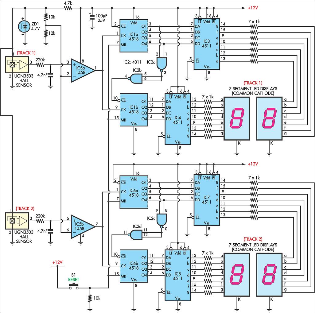
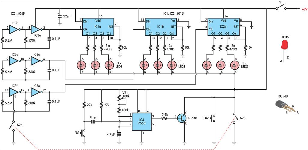
AFX slot car sets are enjoyable, and the experience can be enhanced with a lap counter. This circuit counts from 00 to 99, featuring independent counters for each track. The sensing device utilized is a Hall effect sensor (UGN3503;...
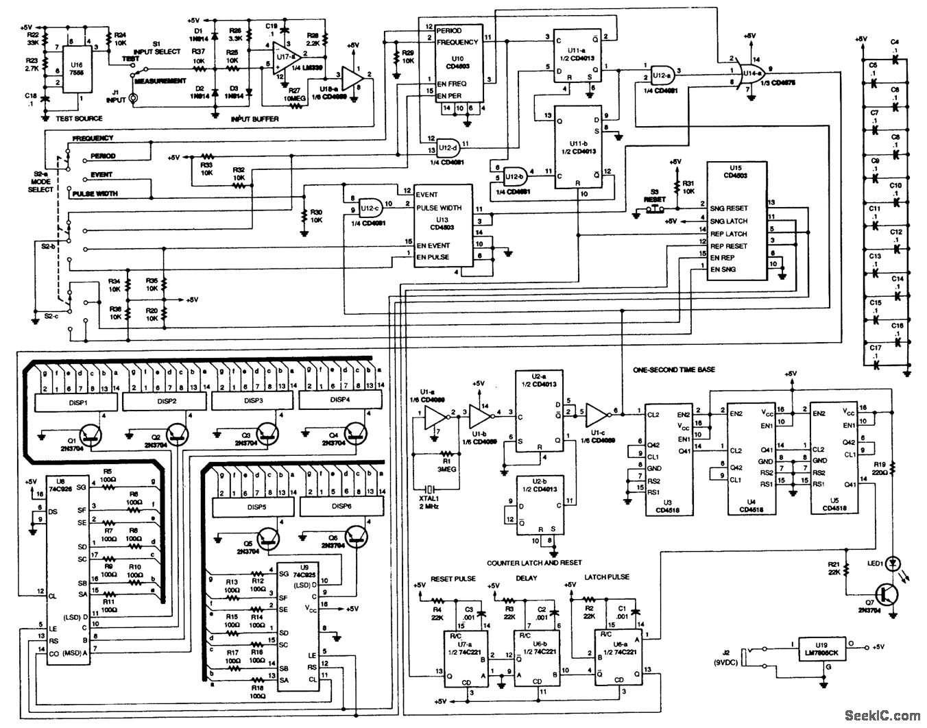
This counter is capable of measuring frequencies ranging from 2 Hz to 1 MHz, as well as time intervals, periods, and counting random events. It utilizes the 74C926 and 74C925 integrated circuits as the primary counting components, which drive...
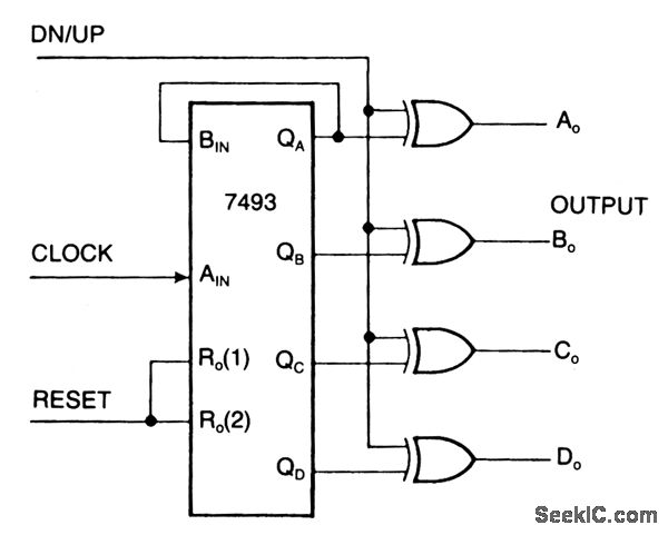
An ordinary binary counter, such as the 7493, can be transformed into an up/down counter with mode control by integrating XOR gates (7486) to the counter's outputs. The circuit counts upwards when the DN/UP line is low and downwards...
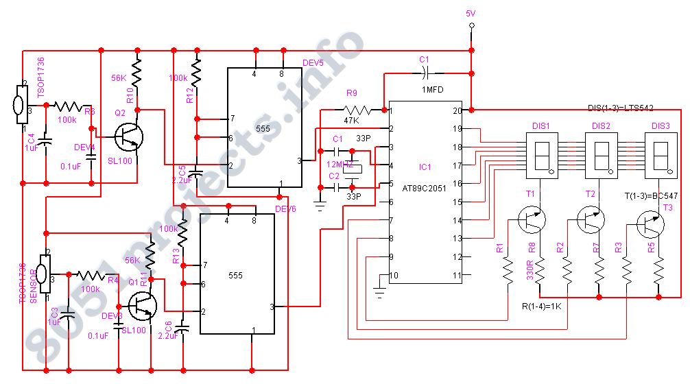
The AT89C2051 Digital Visitor Counter utilizes a microcontroller to perform its function by receiving signals from sensors. The AT89C2051 Digital Visitor Counter is designed to accurately count the number of visitors entering or exiting a designated area. This system employs...
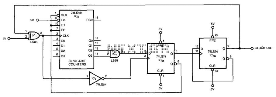
This circuit symmetrically divides an input by virtually any odd number. The circuit contains n + 1 clocks to achieve the desired divisor. By selecting the proper n, which is the decoded output of the 74LS161 counter, divisors from...