
100 MHz RF oscillator with ATtiny12
The described circuit utilizes a Saronix crystal oscillator as a frequency reference for an RS-232 to 100 MHz RF desktop channel adapter. The oscillator's output is configured with an open emitter configuration, which allows for a straightforward method of modulation and signal generation. The circuit employs an Atmel ATtiny12 microcontroller, which is programmed to generate a square wave signal. This microcontroller is a compact and efficient solution, requiring fewer components than traditional timer circuits like the NE-555.
In this setup, a 330 Ohm load resistor is connected to the output of the oscillator. When this resistor is grounded, it enhances the RF output, making it more suitable for RF applications. Modulation control is managed by a transistor, specifically the MPSH34, which is used to switch the load resistor on and off. This gating mechanism allows for dynamic control over the oscillator's output.
The circuit also features a Single Pole Double Throw (SPDT) switch that provides flexibility in modulation input. In one position, the switch connects the square wave output from the ATtiny12 to the base of the MPSH34, enabling the generation of modulated signals. In the alternate position, an external modulation source can be applied. If no external modulation is connected, the circuit defaults to maximum RF output due to the presence of two 10K pull-up resistors connected to the transistor's base, ensuring that the MPSH34 remains in an 'on' state.
This design approach is particularly advantageous for applications requiring a compact and efficient modulation scheme, and it can be adapted to work with other oscillators that necessitate an external pull-down resistor on their outputs. The overall configuration emphasizes simplicity and functionality, making it a practical solution for RF signal generation and modulation in various electronic projects.A frequency reference for tuning up the RS-232 to 100 MHz RF desktop channel adapter elsewhere on this site, when I found this Saronix crystal oscillator in my junk box. A few minutes with AVRStudio produced an ATtiny12 to make a tone - even fewer parts than using an NE-555.
With the addition of a transistor to gate the output, I was set to go. Quick and dirty, but it was useful. The Saronix oscillator has an open emitter output. When the 330 Ohm load resistor on the output is grounded, the RF out of the oscillator increases. Modulation is affected by driving the MPSH34 on and off to switch the 330 Ohm load resistor. An Atmel ATtiny12 provides a square wave signal that can be used to drive the MPSH34, or if the SPDT switch is in the other position, an external modulation source can be used to modulate the signal, or if nothing is connected to the modulation input, the RF output is at maximum value because of the two 10K pull-up resistors on the base of the MPSH34. This technique should work with an oscillator that requires an external pull-down resistor on its output.
🔗 External reference
Related Circuits

The phase shift oscillator is selected as an initial example as it clearly illustrates the principles discussed in the previous blog post. The circuit diagram emphasizes the amplifier and feedback network. It consists of a common source FET amplifier...

This is a simple scheme for a bridge oscillator. It provides a nice sinusoidal signal. This type of oscillator uses an op-amp. The weakening of the oscillating member (R1, R2, C1, C2) is 3x. To compensate, the attenuated signal...
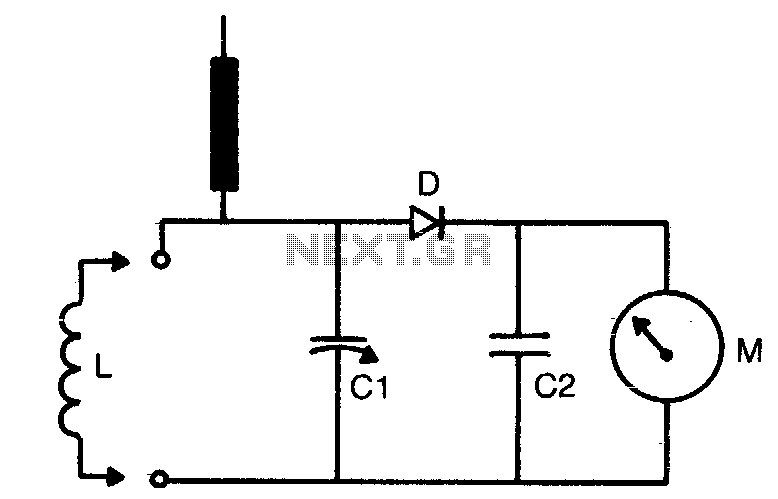
The tuning range is determined by the dimensions of the coil (L) and the setting of the capacitor (C1). Coils can be either plugged in for multi-range use or soldered in place if only a limited frequency range is...
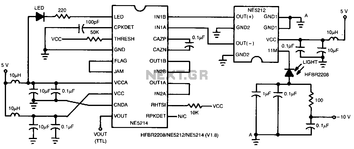
This two-chip receiver, designed for low-cost fiber optic applications at 100-M baud (50 MHz), features a minimal external component count. The receiver consists of pre-amplifier and post-amplifier integrated circuits (ICs) for enhanced stability. The preamplifier IC is characterized by...

The following circuit illustrates a 10.7 MHz RF amplifier and filter circuit diagram. Features include significant capacitances of a power MOSFET. The 10.7 MHz RF amplifier and filter circuit is designed to amplify radio frequency signals while simultaneously filtering out...
This is a sine wave oscillator circuit, also known as an amplitude-stabilized sine-wave oscillator. It can provide a high purity sine wave output. The sine wave oscillator circuit is designed to generate a stable and high-quality sine wave output, which...