
100 watt DC servo amplifier by Power MOSFET
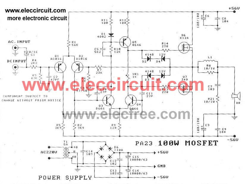
The MOSFET power amplifier circuit employs an OCL configuration, which eliminates the need for output coupling capacitors, thereby improving low-frequency response and overall efficiency. The choice of MOSFETs, such as the K134 and J49 or the J162 and K1058, is critical for achieving the desired power output and fidelity. These MOSFETs are selected for their high gain and low on-resistance characteristics, which contribute to the amplifier's performance.
The circuit typically consists of a differential input stage, which amplifies the audio signal, followed by a voltage gain stage that drives the output stage. The output stage is composed of complementary MOSFET pairs that allow for efficient push-pull operation, minimizing distortion and maximizing power output. The amplifier is designed to operate with a power supply of ±56V, which provides sufficient headroom for dynamic audio signals while ensuring that the output stage can deliver peak power without clipping.
In addition to the MOSFETs, the circuit may include biasing networks, feedback loops, and protection mechanisms to ensure stable operation under varying load conditions. Proper heat dissipation measures, such as heat sinks, are also essential to prevent thermal runaway and ensure reliable long-term performance.
Overall, this MOSFET power amplifier circuit is suitable for high-fidelity audio applications, providing robust power output and excellent sound quality when driving 8-ohm speakers.This is circuit MOSFET power amplifier OCL, Output 100w , use mosfet k134+j49 or Mosfet J162 + K1058, Output 112W at Speaker 8 OHM. Power Supply +56V/-56V 4A.. 🔗 External reference
Related Circuits
This wattmeter circuit has a measurement range of up to 1 kW. It is capable of providing complete (X)(Y) function with the use of only one transistor. The circuit is designed for operation with 117 Vac ±50 Vac. Modifications...
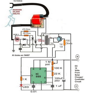
A fence charger or energizer is a device used to electrify a fence or boundary to protect the premises from human or animal intrusions. These boundaries are often located in large fields and parks, typically away from urban areas,...
To configure the amplifier, set resistor R1 to its maximum value and resistor R12 to zero. After this adjustment, power on the amplifier. Adjust R1 until the measured output offset is between 30 mV and 100 mV. Once this...
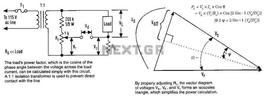
The load's power factor, defined as the cosine of the phase angle between the voltage across the load and the load current, can be calculated using this circuit. An isolation transformer with a 1:1 ratio is employed to prevent...
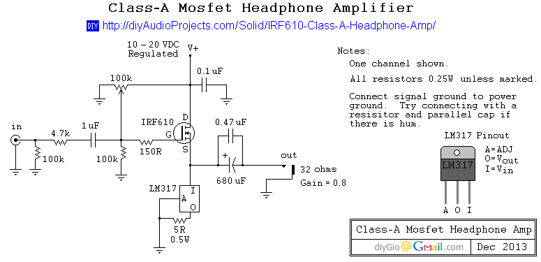
Unsatisfied with the performance of a computer soundcard driving 32-ohm Grado SR80 headphones, a decision was made to construct a desktop headphone amplifier for office use. While ample voltage gain was available, the soundcard struggled with high-quality headphones. This...
This is a simple circuit for a magnetic pickup phono preamplifier. The circuit provides appropriate loading to a reluctance. Here is the circuit: The gain... The magnetic pickup phono preamplifier circuit is designed to amplify the low-level audio signals generated...