
Ac Watts Calculator Circuit

It is advisable to exercise caution when working with voltages of this magnitude in a test setup, even though the measured voltages are typically below 1 V. Rs serves as a circuit-sense resistor, while Rr is a multi-turn potentiometer. The voltage across Rr is approximately 0.5% of the line voltage, which is generally adequate for most applications. Rr is adjusted so that V = tFj, allowing for the measurement of Vd. According to Kirchhoff's voltage law, the vector diagram illustrates that Vs, Vd, and Vr form a triangle, which becomes isosceles when Rr is adjusted. Vs is in phase with the load current, while Vr is essentially in phase with the load voltage.
The circuit design focuses on accurately measuring the power factor by analyzing the phase relationship between the load voltage and current. The use of a 1:1 isolation transformer not only enhances safety by isolating the measurement circuit from high voltages but also reduces the risk of ground loops and noise interference that could affect measurement accuracy. The circuit's configuration allows for the precise adjustment of Rr, ensuring that the voltages Vs, Vd, and Vr align correctly to form the desired isosceles triangle in the vector diagram.
In practical applications, the circuit can be utilized in various settings where power factor measurement is critical, such as in industrial systems, power distribution networks, and residential electrical systems. The careful selection of Rs and the multi-turn potentiometer Rr facilitates fine-tuning of the circuit to accommodate different load conditions and voltage levels. This methodology provides a reliable means of evaluating the efficiency of electrical systems, as a power factor closer to unity indicates optimal performance, while lower values suggest inefficiencies that may need to be addressed. Overall, this circuit serves as a valuable tool for engineers and technicians in the field of electrical engineering, enabling them to perform accurate power factor measurements and improve system performance. The load`s power factor, which is the cosine of the phase angle between the voltage across the load current, can be calculated simply with this circuit. A1:1 isolation transformer is used to prevent direct contact with the line. By properly adjusting Rr, the vector diagram of voltages Vs, Vd, and Vr forms an isosceles triangle, which simplifies the power calculation.
The method basically consists of determining the power factor of the loadthe cosine of the phase angle between the voltage across the load and the load circuit. Using a simple circuit, that angle can be calculated quite simply. This circuit uses a 1:1 isolation transformer to prevent direct contact with the line. It is wise to proceed with caution whenever voltages of this magnitude are utilized in a test setup, even though the voltages that will be measured are usually below 1 V. Rs is a circuit-sense resistor and Rr is a multi-turn potentiometer. The voltage across Rr is approximately 0.5% of the line voltage, which should be sufficient for most applications, Rr is adjusted so that V = tFj; then Vd is measured.
In the vector diagram according to Kirch-hoff`s voltage law, Vs, Vd, and Vr form a triangle, which becomes isosceles by adjusting Rr. Vs is in phase with the load current and Vr is essentially in phase with the load voltage.
Related Circuits
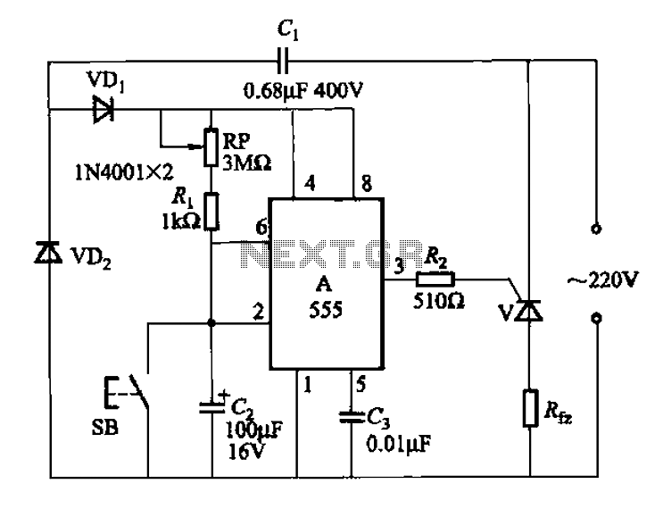
The 555 integrated circuit (IC) is utilized in a delay circuit configuration. It transitions from a high to a low output state when a button (SB) is pressed. The output remains high for a specified delay period before transitioning...
For bikers or scooter riders, it is common to forget to cancel flashing indicators after making a turn, especially without an audible reminder. Continuously checking indicator lamps is impractical, as attention should remain focused on the road. The circuit...
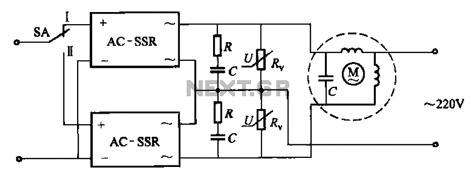
The circuit illustrated in Figure 3-14 features a SA switch positioned in the work state, allowing for motor operation. When the SA switch is set to the reverse position, the motor's direction is inverted. Additionally, an over-voltage protection element...
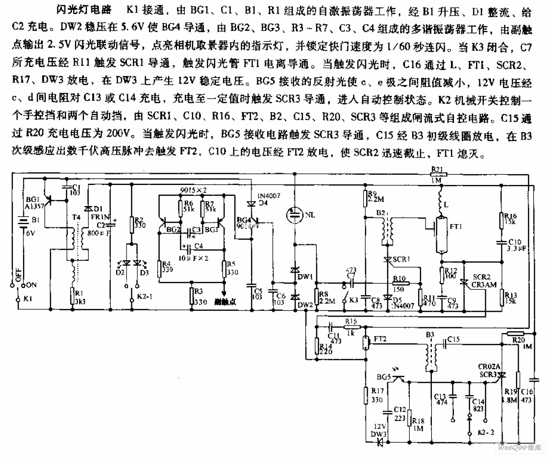
The camera flashlight circuit activates when switch K1 is engaged. This triggers a self-oscillating circuit consisting of BG1, capacitor C1, battery B1, and resistor R1. Once operational, the circuit boosts the voltage through B1 and rectifies it using diode...
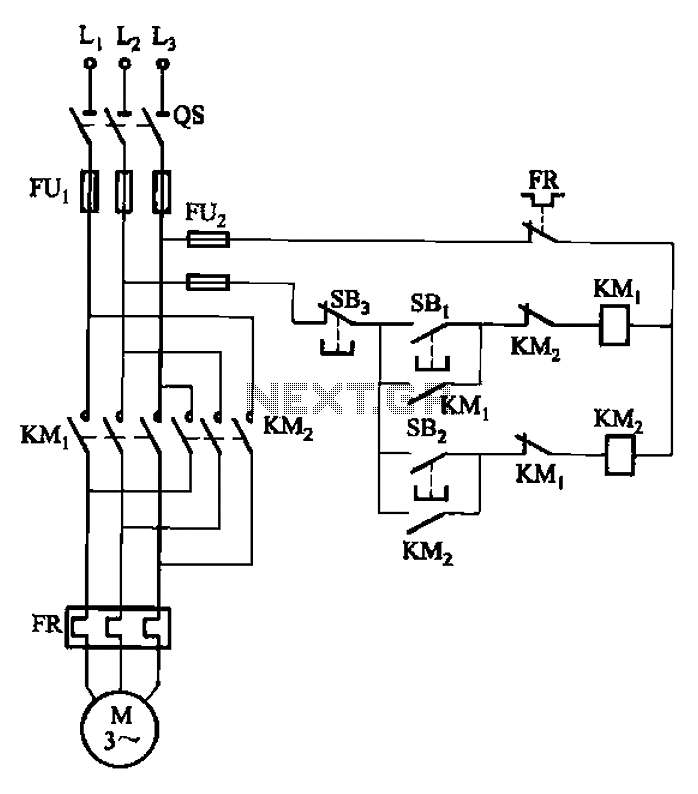
The circuit depicted in Figure 3-22 includes KMi and SBi as forward contacts and forward buttons, KMz and SB2 as reverse contactors and reverse buttons, with SB3 designated as the stop button. The circuit in question is likely part of...
This page presents a replacement circuit for the LM3909 LED Flasher/Oscillator utilizing discrete components. The circuit functions similarly to the integrated LM3909 but features minor variations in the component values used. Although the LM3909 is still available, it tends...