
1000 m single-tube FM transmitter circuit diagram of oscillation

The circuit diagram for a 1000 m single-tube FM transmitter is designed to generate frequency modulation signals suitable for transmission over a distance of approximately 1000 meters. This transmitter employs a single vacuum tube, which serves as the primary active component to facilitate signal oscillation and amplification.
The circuit typically includes a power supply section, which provides the necessary voltage and current for the tube operation. A common configuration utilizes a high-voltage power supply, often in the range of 90 to 250 volts, to energize the tube. The tube operates in a Class C configuration to maximize efficiency and output power.
The input signal, which is the audio or data to be transmitted, is fed into the grid of the tube through a coupling capacitor. This capacitor blocks any DC component while allowing the AC audio signal to modulate the carrier wave generated by the tube. The modulation occurs as the tube's conduction varies with the input signal, resulting in frequency variations of the carrier wave.
An LC tank circuit, composed of an inductor and a capacitor, is used to determine the oscillation frequency of the transmitter. The inductor is typically connected to the plate of the tube, while the capacitor is connected to ground. The values of these components can be adjusted to tune the transmitter to the desired frequency within the FM band.
A key aspect of the circuit is the output stage, where the modulated signal is coupled to an antenna. This is often achieved through a matching network that ensures maximum power transfer and minimizes signal loss. The antenna itself should be designed for the specific frequency of operation to achieve optimal radiation efficiency.
To enhance performance and stability, additional components such as resistors and bypass capacitors may be included to control gain and reduce noise. Proper layout and shielding techniques should also be employed to minimize interference and ensure compliance with regulatory standards for radio frequency emissions.
Overall, this single-tube FM transmitter circuit is a straightforward yet effective design for generating FM signals suitable for short-range communication applications.1000 m single-tube FM transmitter circuit diagram of oscillation:
Related Circuits
Typical segment display LEDs consume around 25 mA for each segment and should be limited to this current with resistors. For a six-digit display to be current limited, at least 42 series resistors are needed. The brightness of the...
This circuit features a microphone and preamplifier that take precedence over any other audio signal, functioning similarly to a one-way intercom. When the push-to-talk switch is activated, the main amplifier switches from music playback to the voice signal. Essentially,...
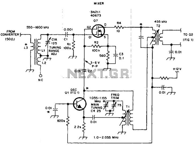
This circuit is an enhanced front end for upgrading a transistor AM receiver. This front end is beneficial when the radio is intended to function as a tunable IF amplifier with shortwave converters. The circuit described serves as a sophisticated...

The design's value is derived from the use of IC1, an LM317HVK adjustable series-pass voltage regulator, which provides broad-range performance along with voltage-setting and current-limiting functions. The input to IC1 is sourced from the output of BR1, which is...
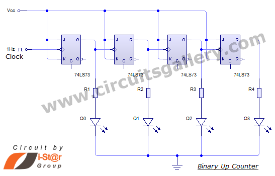
This document discusses an Asynchronous 4-Bit Binary Up Counter, a circuit constructed from several J-K flip-flops connected in a cascade configuration to produce a four-bit counting sequence. An up counter is a digital counting circuit that increments its count...

A stepper motor controller based on schematics available on the Arduino website. Initially, a two-pin configuration was attempted for a bipolar stepper motor, but it did not function as expected, especially with the library provided on the site. The...